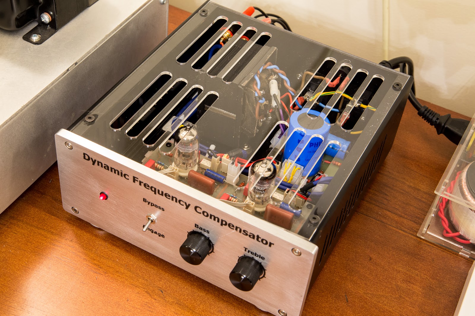
A long time ago we did a scrapyard project with leftover and foraged parts, it was an active Tone Control (you can read about it here) that was just intended as a working proof-of-concept for the tone control that we use in our Octantis and Kingsway models.
This unit was never in production; it was just a rough working test.
And yet… it has been the page that constantly gets the most hits on this site, and the most requests by email.
So, in this post we are announcing our intent to design a new version of the standalone tone control, functionally similar to the prototype but in a more cosmetic package.
Features list:
Bass and treble controls offering ±12dB of adjustment at 100Hz and 10KHz (non-parametric)
Switchable ON or BYPASS
Powered by 12volt external power supply
2-tube design
Stereo RCA input and output sockets
Mode indicator LEDs
Can be left in circuit continuously; if powered off will automatically enter BYPASS mode
Our schedule is to have it available by Christmas 2023; pricing yet to be finalised, we’re aiming for a price point at or under $400 if possible.
Back in 2018 when our integrated amplifier was first designed, the name Matariki suggested itself because it was designed during the winter months and completed during Matariki season. Co-incidentally, Wellington Harbour was visited by a Southern Right whale at that time which was named Matariki owing to the timing of its visit.
Our amplifier was actually named after the whale.
Times have moved on, that whale’s visit is history now, and Matariki has taken more of a dominant view in the public discourse in Aotearoa New Zealand.
ATRAD-Audio has no desire for any of our products to be seen as commercially exploiting something of deep cultural significance, so in future our integrated amplifier will no longer be sold as the Matariki.
So, starting from June 2023, and continuing the astronomical theme, the Matariki will now be known as the Octantis.
Everything else about it will remain the same, just the name will change.
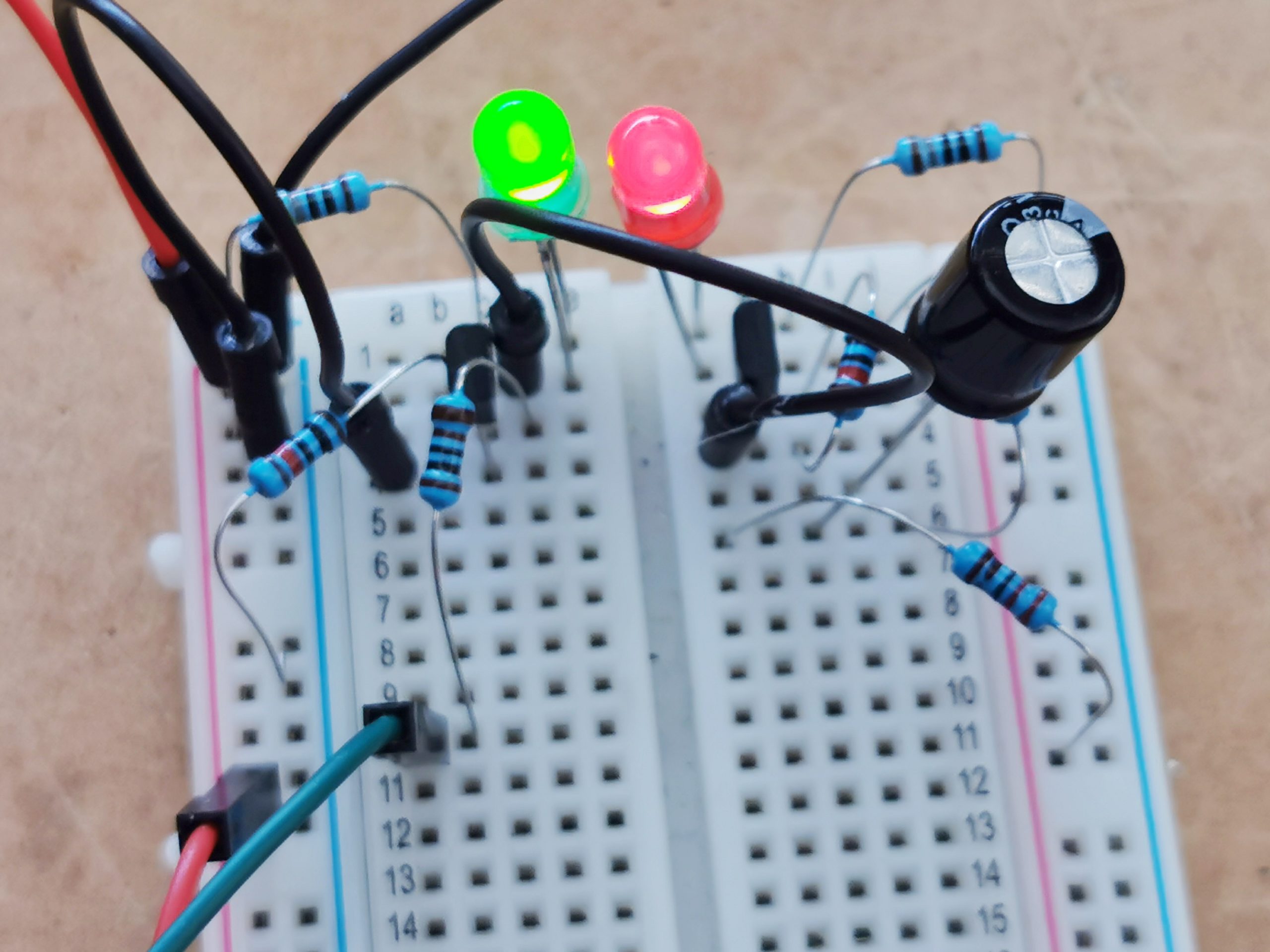
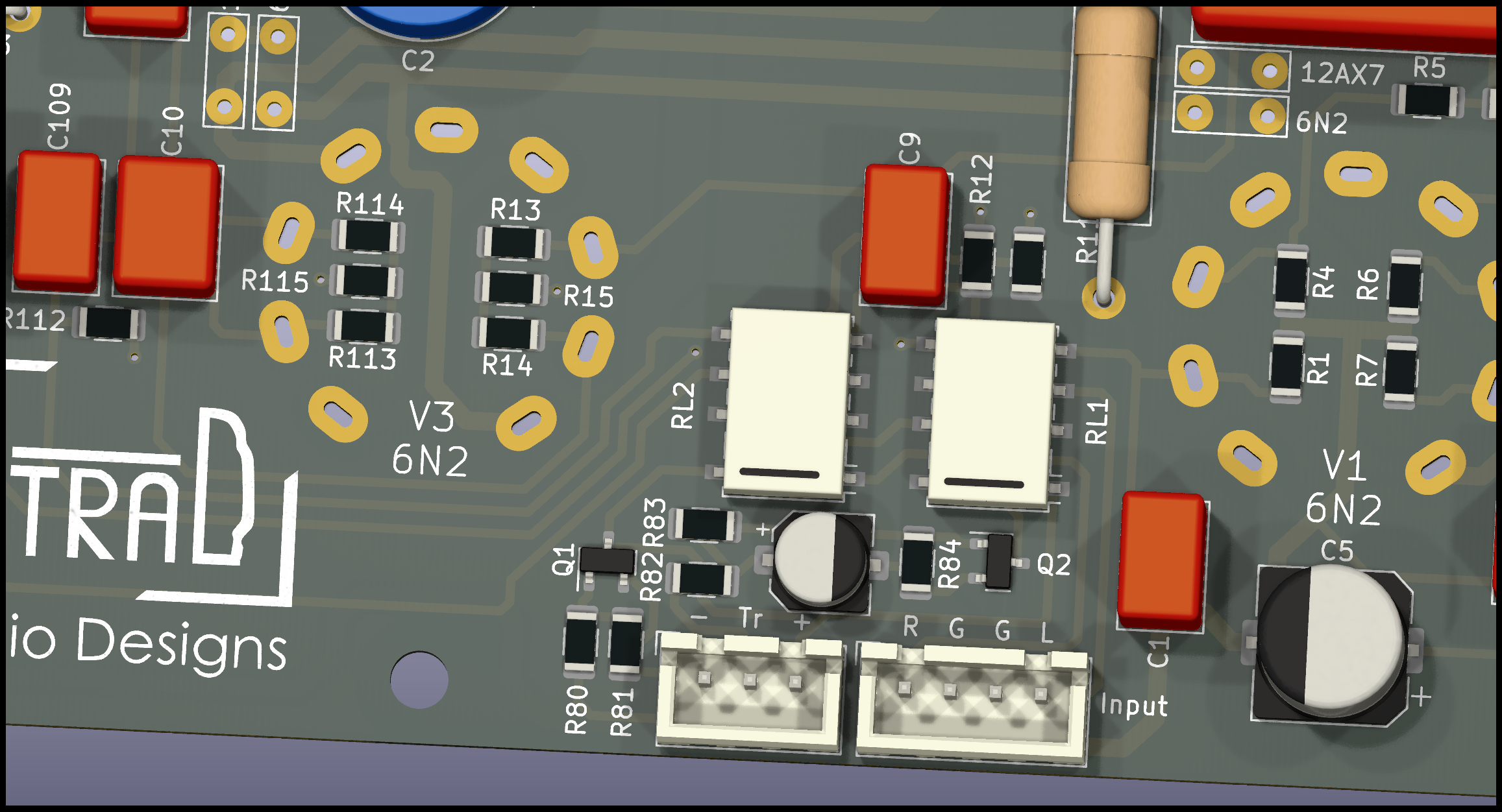
The Idea came from darkness, without Form or Substance. So the Designer conceived forth the idea on the Breadboard and breathed life into the creation:
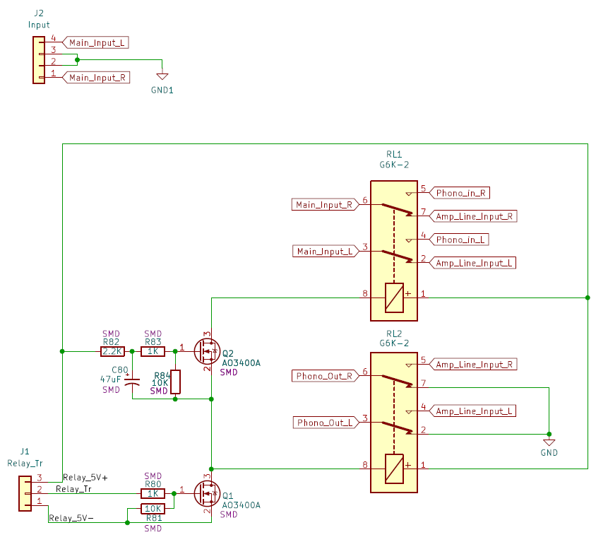
It was a mess, and the people did look Puzzled, and cried unto themselves “what the hell is this?”. So the Designer brought forth the Schematic:
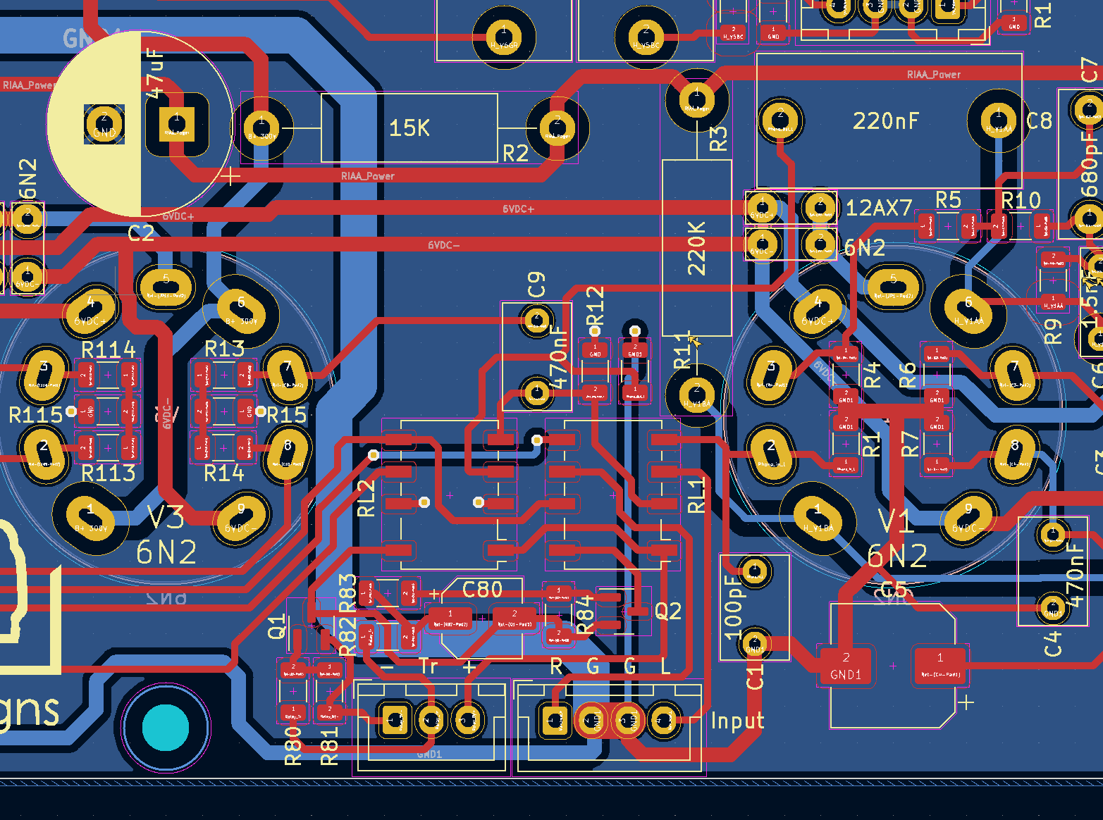
And the people saw the Schematic, and agreed it was good. And did nod amongst themselves sagely, saying unto the Designer “Now show us your PCB Design”. And the Designer did think longly and deeply about it, and then brought he forth the Layout:
And while the Layout did pass all the Design Rule and Schematic Parity checks, all around were still confused, and darkness remained upon their faces. So the Designer then brought forth the Render, and all were sore amazed:
And thus did the designer finish triumphantly, exclaiming “Well it better bloody work!”
And that is how PCBs are made.
But what’s it for?
Glad you asked. I want these two relays to turn on in sequence, about 100ms apart, but turn off together. For switching between Line and Phono inputs without the loud “pop” at the moment of contact.
When I breadboarded the circuit, I decided to sub in some LEDs for the relays, for better visualisation. Here is the result:
Those in the vacuum tube/valve amplifier game, particularly in Australia, will probably have heard of Patrick Turner. His site turneraudio.com.au was full of information and an often-cited reference for many, written in a style and with a humour that was uniquely Patrick’s.
Many projects were presented, with background information, theory and construction information all tightly jammed in together. The man was a goldmine of information and his knowledge was guru-level.
I had some conversations with Patrick in 2018/19. During that time, he implored me to take a copy of his site, as he was not sure how long he had left, being elderly and in poor health. This was a subject he wrote about on his site as lucidly as though it was a broken radio that needed diagnosing and fixing!
Patrick died in May 2021; his site is offline now.
In tribute to Patrick and his rich legacy of work, I’ve put up the scrape I did of his site with no changes whatsoever
Ever since people started playing with electronic equipment in the early 20th century, it’s been known that electronic equipment runs on smoke. If the smoke escapes, the equipment stops working.
Sometimes, the manner of the smoke escaping is discreet and quiet, other times it escapes forcefully.
Whilst it is said that any machine can be a smoke machine if you operate it wrong enough, it is none the less desirable for machines to refrain from letting their magic smoke out (either explosively or otherwise) in normal operation.
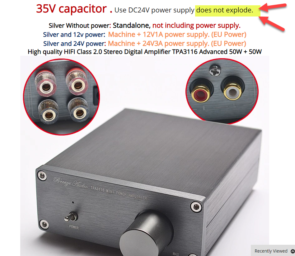
Clearly this principle has resonated with other manufacturers, as a quick look on Aliexpress reveals among the list of features for this equipment
Not Exploding is an attribute we look for in electronic equipment. This manufacturer seems proud to advertise the fact
Accordingly we introduce the DNE certification mark: DNE for Does Not Explode.
Henceforth all our amplifiers will be carrying this mark.
The other day I got an email from Spotify which very neatly illustrated the problems that classical music present to streaming platforms or personal media servers:
Last I knew, Chopin has been dead for at least 170 years. Very clever of him to be releasing fresh tracks while decomposing.
In Classical music we tend to focus more on “Works” not Tracks.
A Work is created by a composer. It may consist of one or more tracks. A work may stand on its own, or be part of a collection.
A work is different from an Album – albums are not really a thing in classical music. Back in the days when CDs were king, one CD could contain more than one work, if they were short. Usually works for such compilation CDs were selected with some theme in common, such as same performer, same composer or similar.
Conversely, one long work could also span several CDs, such as the Verdi Requiem, for example.
Non-classical is easy. For example, there is only one “No Jacket Required” album and it’s by Phil Collins. Very easy to categorise and search. Conversely for any one particular classical Work there are usually multiple recordings available, and for the more popular works like Vivaldi’s Four Seasons or Beethoven’s 5th symphony, there are hundreds of different recordings.
Each work is of a particular type: Symphony, choral symphony, opera, concerto, to name a few.
Each different recording of a work has different performers. Typically the credits will include the conductor, the orchestra (if it’s an orchestral work), the soloist (if it’s a concerto) and the vocalist(s) if it’s operatic or choral, and all the performers if it’s chamber music or a solo piece (like the Bach cello suites). Also the venue in which it was recorded.
On top of that each work has a genre – naive music libraries tend to lump them all into “classical” but as with all types of music, there are many sub and sub-sub genres.
Most classical music – especially symphonies and concertos – contain individual movements (aka tracks) which have the same name as tracks in other works, because the naming convention tends to be the italian name for the tempo of the track. (“Presto”, “Allegro Assai” etc) – so the individual track name is meaningless without knowing which work it belongs to, and moreover which performance of which work.
From all this it should be clear that putting together a well organised classical music library is a somewhat more complex undertaking than simply putting a bunch of folders together, ripping a bunch of CDs and putting each CD into its own folder, and hoping for the best!
These concerns are all equally valid for streaming services like Spotify and Tidal and others. Clearly in the example above, someone has released a new recording of a Chopin work, and the “album artist” tag is set to “Frederic Chopin” – hence the email.
Clever Chopin, dead for 170 years, buried in Paris and his heart buried in Poland, yet still churning out the hits!
With non-classical music it’s way easier. Enter “Phil Collins” into the search, and you get a list of all Phil Collins’ albums (sorted by year if you’re lucky!)
Classical? Not so much.
Questions I might want to ask my classical music library:
Show me all the Beethoven symphonies in my library (I’m querying Works by composer and Work Type) – I expect to see a list of works that meet the criteria, with information about each work that makes it unique (eg year of recording, conductor/orchestra, venue, etc). Clicking on each work should then explode it into its individual tracks/movements (and these need to be in the right order too, shuffle is not a thing for classical!)
Or I could perhaps have been taken with a particular singer’s voice. Carolyn Sampson did a magical recording of the Bach secular cantatas and perhaps I might want to see what else she’s done. This is a search by performer and once again I want a list of works, this time where she’s credited as the singer.
You can think up any type of query based on work, composer, work type, genre, performer, collection etc, and you should be able to find it easily. The key here is that the defining classification in all these cases is the work, not the album. Yet the metadata tags for music files don’t even contain a “work” field!
Perhaps this gives a clue as to why classical music tends to confound streaming services and bedevil people who curate their own media collection. My media server software (Plex) doesn’t stand a ghost of a chance against this complexity. It’s firmly rooted in the “one artist per album… list the albums per artist” philosophy. It doesn’t even support displaying or searching by Composer, and has no clue what a “work” is.
Where to from here? Perhaps Roon might be worth a second look… I had a trial, but was discouraged by the cost.
What do other classical music fans do, who want to manage their library electronically, I wonder?
Largely owing to convenience of supply, I’ve made my last few builds with Russian triodes instead of Western ones. These are in plentiful supply as NOS from the 70s and 80s, and available cheaply on eBay and other sources. Typically these are military-spec and quite consistent in quality, so they are fantastic for audio.
Some of them are pretty much direct equivalents (eg. 6N2 for 12AX7, 6N6 for ECC99) while others are close but not quite the same, meaning any circuit would need to be recalculated if subbing in a Russian tube.
This is relevant because most tube audio schematics I’ve found on the internet are specified with Western types, some of which have no direct equivalent.
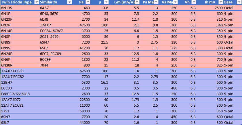
So to bring several sources of information together in one handy reference, I made a spreadsheet which lists the different tube types and their vital parameters.
Red are Russian types, blue are Western. Click to see larger
To make things easier I made it into a table so you can sort and filter it in Excel. You can download the original file here
One thing worth remembering. The pinouts are different, specifically, for the filaments (heaters) so you can’t just drop a Russian tube in place of an equivalent as shown in the table above. Some re-configuring would be necessary.
Since I started building amplifiers, I’ve been reliant on one supplier in particular, for my chassis and casework.
Most suppliers of parts can be replaced – however when you’re sourcing outwork services you enter into a relationship with your supplier that goes beyond a straight customer / supplier dynamic.
Introducing Embrace Design who have provided all the CNC and laser cutting and engraving services for the cases for my amplifiers. The service doesn’t stop there however. Henri has been a rich source of suggestions and ideas and has been completely cooperative in working with me to get exactly the look and aesthetics I have been looking for, as well as a good emergency weekend source of fasteners and other necessities. Much of the exterior appearance of my amplifiers is down to Henri’s skill with translating the designs into reality. Worth acknowledging here.
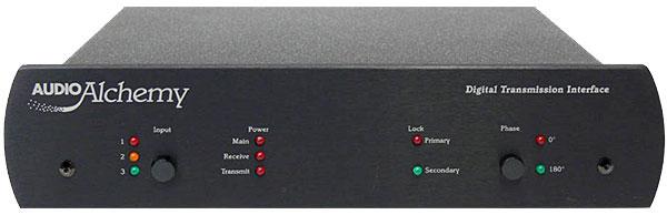
… in which I make myself unwelcome at a high-end hi-fi store. This is a personal experience which happened over a decade ago, but I decided to put it here because it’s still relevant. These are the two products in question
Audio Alchemy Digital Transmission Interface, US$ 1600
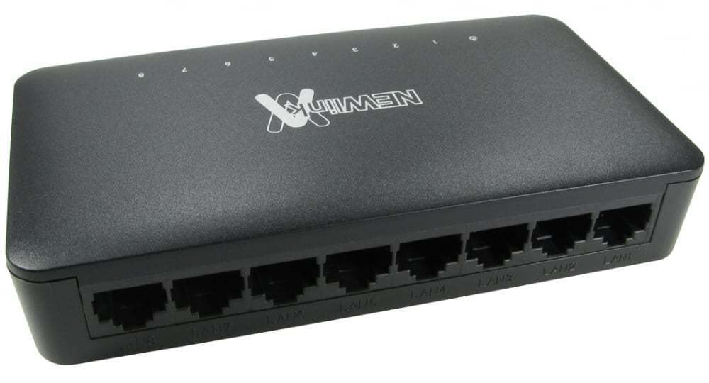
Generic 10/100 8-port auto-sensing ethernet hub, around US$ 40 – 60 (at the time) depending on brand.
On the day in question, I walked into a hi-fi shop and the proprietor greeted me with a wide smile. This was a real high-end place where the demo systems are set up with speaker cables as thick as fire hoses, and just the rack that the system is sitting on has a five-figure price ticket. We got talking (this was years before I started designing and building gear myself, I was just looking at buying a new pair of speakers which is what drew me into the shop). Pretty soon he had figured out my system and had decided that it would be improved by the addition of the top product, above. While extolling its many and varied virtues, he inadvertently tripped himself up by completely inaccurately describing the phenomenon of jitter … seems he hadn’t read up enough on the technical manual that accompanied the product. After a little while, I attempted to summarise my understanding of this product back to him, to show him I’d been listening. He was all ready to sell me one until I started asking some questions which led me to explain the function of the second pictured device…
Conversation went something like this: “So, this machine will take a PCM data stream at 1.4 megabits per second (Red Book CD standard), store and buffer it, then output an identical data stream according to its own internal clock, which is carefully designed to be high-accuracy and not susceptible to disruption, correct?”
“Yes, and [long spiel about how that makes it sound better, yada yada]”
“And it’s $2200.” [That was the $NZ price at the time]
“Yes, possibly the best value enhancement you can make to a digital system…..”
“OK, so what then would you say about a device that does this at around 70 times the data rate, and not for one but eight separate inputs?”
“Well the DTI represents the cutting edge of digital transmission design, so perhaps in the future something might be designed that could do what you say, but it would be a very high-end piece of equipment, so only the most serious audiophiles would require it, and that’s assuming there’d ever be a digital recording standard that would utilise such a bit rate”
“So you’re saying it’d be expensive then?”
“Something with over 500 times the processing capacity of this machine? Very!”
At which point I explained the functionality of the 10/100 ethernet hub, and then its price. He wasn’t smiling any more.
In fact, I got the distinct sense I’d outstayed my welcome in that establishment.
– This is why I don’t go into high-end hi-fi stores any more. –
Update Dec 2021: Since the above mentioned product is long-discontinued, it stands to reason that its absence has left a hole in the audiophool world. And, an enterprising company has identified this (perhaps they came here first?) and we now have a $2,500 ethernet switch. Audiophiles, never fear. You won’t have to endure that burning sensation from all that cash in your pocket any longer.
The push-pull design for output stages has persisted since times of antiquity. It was one of the very earliest circuit designs, and has persisted until the present day, with modern solid-state linear amplifiers still overwhelmingly using it.
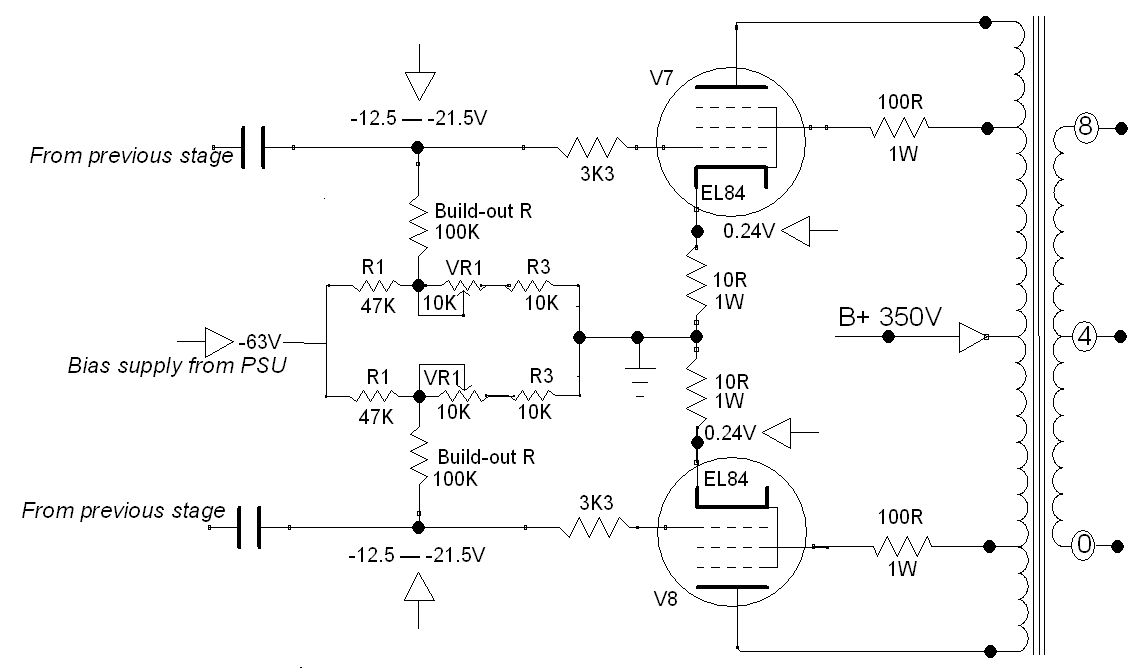
With tubes, a typical topology is given by the circuit below. (Click to magnify). The anode (plate) voltage on either side comes through the primary of the output transformer. This design uses a pentode tube, which has a screen grid. This is attached to taps on the output transformer to run in Ultra-Linear mode, increasing efficiency and reducing distortion.
In this design, the cathodes are tied to ground through a very low value shunt resistor. The resistor is simply there to provide a small voltage drop from which the current through the tube can be measured. It plays no other role in the circuit, other than being a fuse if the tube red-plates.
Values of one ohm or ten ohms are typical of this arrangement.
Typical implementation of a Fixed-bias, ultralinear Push-Pull output stage with a pair of pentode tubes (EL84 / 6BQ5)
Because the cathode is at (or very close to) ground potential, this requires the control grid to have a negative DC bias voltage applied to it, to regulate the flow of current through the tube.
If there was no negative bias applied to the tube, it would go into full conduction, the plate would glow red hot, fireworks will happen and that would be Bad, mmkay? So we need to contrive to feed a constant negative voltage into the grid, along with the signal, to achieve the desired regulation.
The voltage required depends on several factors… as a very rough rule-of-thumb, take the screen voltage and divide it by the tube’s mu (gain) to get the maximum negative bias voltage likely to be needed
Looking at the circuit above… An EL84 has a mu of 20 and in this implementation the screen voltage is 350 (in Ultra linear we take the screen voltage as the same as the anode/plate voltage), which gives us 17.5 volts. Multiply by -1 since we’re dealing with negative volts. So we’re likely to need around -17.5 volts.In this case, our adjustment range is from -12.5 to -21.5 volts.
How to set up the bias adjustment resistor values The bias voltage needs to be adjustable. Both tubes need to be drawing the same current, otherwise the net current through the transformer will not be zero, which will lead to magnetisation of the transformer core. This is a most undesirable situation and left unchecked, it will cause quantum fluctuations in the space-time continuum. Well ok maybe not that bad, but the transformer will saturate unevenly and distort the sound.
The usual approach is to use a voltage divider network with a potentiometer, as above. Couple of points about this design.
The more negative the voltage goes, the lower the current through the tube
In this implementation, if the potentiometer fails, it will fail safe. The most common mode of failure with potentiometers is the wiper lifting off the track. If this happens, effectively the voltage at the grid of the tube will go full negative, reducing the current through the tube to (almost) zero. This is far more desirable than the voltage reaching zero and the tube immediately red-plating.
Expanding on (2) – please don’t ever build this circuit with just the pot wiper connected to the grid. When the pot fails (and it will, eventually) it’ll likely take the tube with it.
If you’re going to build this circuit, it’s intuitive to set it up so that clockwise rotation of the pot increases the current through the tube (ie brings the biasing voltage closer to zero)
The next question is – what value resistors will be needed? This is where some trial and error in the calculations is needed. Using Ohms’ law, these are the variables:
The desired bias voltage adjustment range
The input negative voltage from the power supply
From there, you can calculate the values for the resistors and potentiometer to give you the range you need.
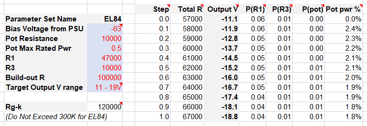
Put in the numbers in the red. Experiment with the values for R1 and R3 and the potentiometer, until you get the desired voltage range in the “Output V” column.
The “Build-Out R” represents the load seen by the preceding driver or phase-splitter stage, so watch the maximum “Rg-k” from the tube’s datasheet isn’t exceeded. In the case of an EL84, that value is 300K. (In the datasheet there will be a specification for this, and it’s diffrent depending on the mode of use of the tube. So look for the “two tubes, class AB” which is in most pentode/tetrode datasheets)
The columns of this spreadsheet:
Step – the setting on the potentiometer
Total R – the total resistance from the bias voltage to ground
Output V – the negative voltage as fed to the control grid
P(R1) – the amount of power dissipated by R1
P(R3) – power dissipated by R3
P(Pot) – the power dissipated by the potentiometer
Pot pwr % – the power dissipated by the pot expressed as a percentage of the pot’s total power rating AND the amount of track being used to conduct.
About Pot pwr % In the specifications for the potentiometer, there will be a power rating. However that power rating is across the entire length of the track. If the pot is set to half-position (assuming it’s a linear taper which in this design it is) then the power handling drops to half. So, this Pot pwr % column shows how much power the pot is dissipating as a percentage of its maximum taking the wiper position into consideration.
Using the circuit Putting all this together, it’s easy to see how it works. Adjust the potentiometer for maximum negative voltage (wiper closest to the left, in this schematic). Power on the circuit and let it stabilize. Measure the voltage across the cathode resistor. Then adjust the potentiometer until the desired current is flowing through the tube.
What is the desired current through the tube? Glad you asked. This depends on the tube itself, and the B+ voltage, and your preference regarding bias.
As a rule of thumb, biasing at around 70% of maximum is the sweet spot with most types when using this conifguration. If you bias low, that’s called “cold” biasing. It means the current through the tube will be low, and the sound may take on a thin, glassy, brittle aesthetic, and the distortion will increase. Bias too hot and you’ll shorten the life of the tubes for no real benefit. 70% is the goldilocks zone. So. Look at the tube’s datasheet. For an EL84 we see the maximum plate dissipation is 12 watts.
70% of 12 watts is 8.4 watts
B+ is 350 Volts
So, using Ohms Law:
we solve for I at 24mA
Across 10 ohms (cathode resistor) our 24mA will give 0.24V
So we want to see 0.24V across the cathode resistor. Adjust the potentiometer until that’s the value shown. Then repeat for the other tube in the circuit, then do a final check that they’re both the same (or as close as you can get)
Please feel free to use my spreadsheet – I developed it to assist in choosing the resistor network values, and also to ensure the power rating of the potentiometer wasn’t being inadvertently exceeded at any setting.