In the beginning, there was the Idea.
The Idea came from darkness, without Form or Substance. So the Designer conceived forth the idea on the Breadboard and breathed life into the creation:
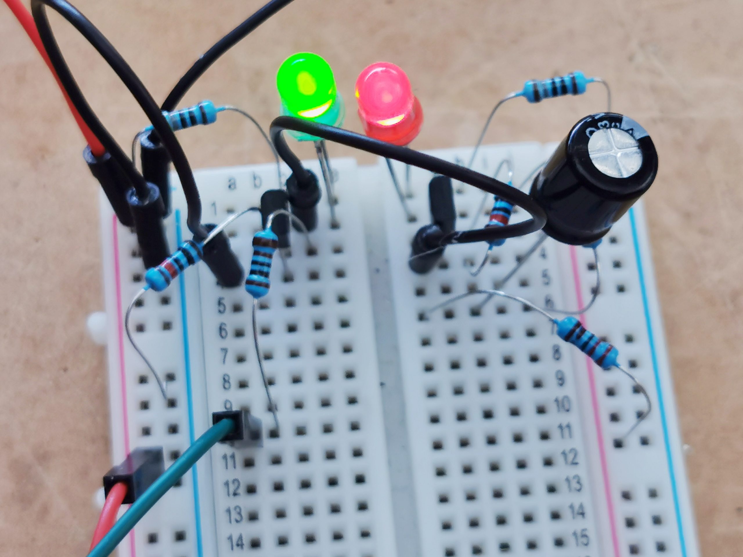
It was a mess, and the people did look Puzzled, and cried unto themselves “what the hell is this?”. So the Designer brought forth the Schematic:
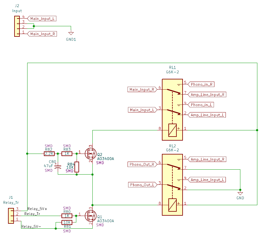
And the people saw the Schematic, and agreed it was good. And did nod amongst themselves sagely, saying unto the Designer “Now show us your PCB Design”. And the Designer did think longly and deeply about it, and then brought he forth the Layout:
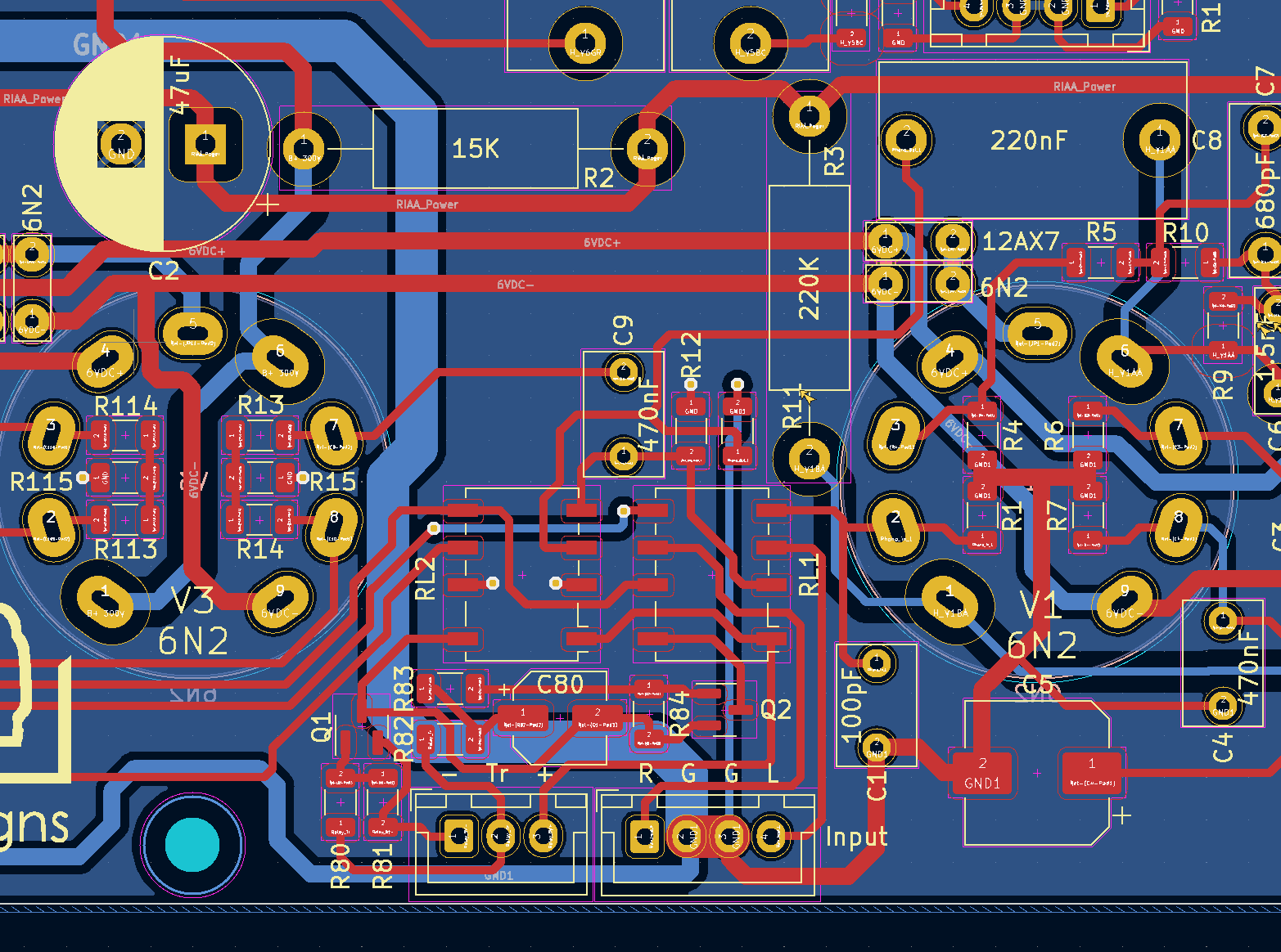
And while the Layout did pass all the Design Rule and Schematic Parity checks, all around were still confused, and darkness remained upon their faces. So the Designer then brought forth the Render, and all were sore amazed:
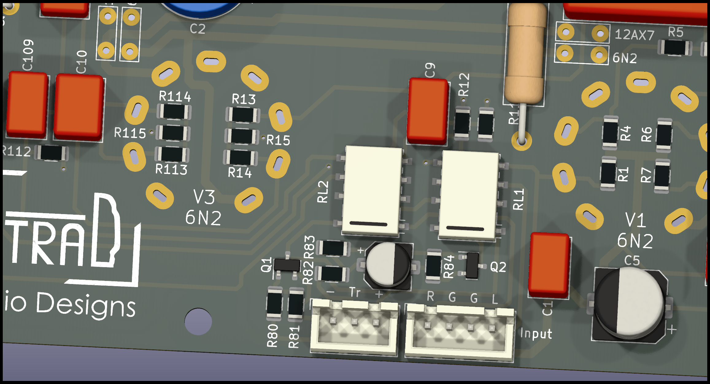
And thus did the designer finish triumphantly, exclaiming “Well it better bloody work!”
And that is how PCBs are made.
But what’s it for?
Glad you asked. I want these two relays to turn on in sequence, about 100ms apart, but turn off together. For switching between Line and Phono inputs without the loud “pop” at the moment of contact.
When I breadboarded the circuit, I decided to sub in some LEDs for the relays, for better visualisation. Here is the result: