Largely owing to convenience of supply, I’ve made my last few builds with Russian triodes instead of Western ones. These are in plentiful supply as NOS from the 70s and 80s, and available cheaply on eBay and other sources. Typically these are military-spec and quite consistent in quality, so they are fantastic for audio.
Some of them are pretty much direct equivalents (eg. 6N2 for 12AX7, 6N6 for ECC99) while others are close but not quite the same, meaning any circuit would need to be recalculated if subbing in a Russian tube.
This is relevant because most tube audio schematics I’ve found on the internet are specified with Western types, some of which have no direct equivalent.
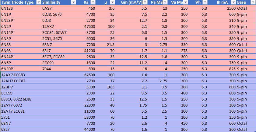
So to bring several sources of information together in one handy reference, I made a spreadsheet which lists the different tube types and their vital parameters.
Red are Russian types, blue are Western. Click to see larger
To make things easier I made it into a table so you can sort and filter it in Excel. You can download the original file here
One thing worth remembering. The pinouts are different, specifically, for the filaments (heaters) so you can’t just drop a Russian tube in place of an equivalent as shown in the table above. Some re-configuring would be necessary.
The push-pull design for output stages has persisted since times of antiquity. It was one of the very earliest circuit designs, and has persisted until the present day, with modern solid-state linear amplifiers still overwhelmingly using it.
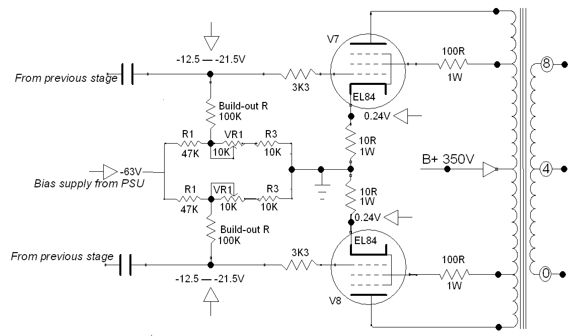
With tubes, a typical topology is given by the circuit below. (Click to magnify). The anode (plate) voltage on either side comes through the primary of the output transformer. This design uses a pentode tube, which has a screen grid. This is attached to taps on the output transformer to run in Ultra-Linear mode, increasing efficiency and reducing distortion.
In this design, the cathodes are tied to ground through a very low value shunt resistor. The resistor is simply there to provide a small voltage drop from which the current through the tube can be measured. It plays no other role in the circuit, other than being a fuse if the tube red-plates.
Values of one ohm or ten ohms are typical of this arrangement.
Typical implementation of a Fixed-bias, ultralinear Push-Pull output stage with a pair of pentode tubes (EL84 / 6BQ5)
Because the cathode is at (or very close to) ground potential, this requires the control grid to have a negative DC bias voltage applied to it, to regulate the flow of current through the tube.
If there was no negative bias applied to the tube, it would go into full conduction, the plate would glow red hot, fireworks will happen and that would be Bad, mmkay? So we need to contrive to feed a constant negative voltage into the grid, along with the signal, to achieve the desired regulation.
The voltage required depends on several factors… as a very rough rule-of-thumb, take the screen voltage and divide it by the tube’s mu (gain) to get the maximum negative bias voltage likely to be needed
Looking at the circuit above… An EL84 has a mu of 20 and in this implementation the screen voltage is 350 (in Ultra linear we take the screen voltage as the same as the anode/plate voltage), which gives us 17.5 volts. Multiply by -1 since we’re dealing with negative volts. So we’re likely to need around -17.5 volts.In this case, our adjustment range is from -12.5 to -21.5 volts.
How to set up the bias adjustment resistor values The bias voltage needs to be adjustable. Both tubes need to be drawing the same current, otherwise the net current through the transformer will not be zero, which will lead to magnetisation of the transformer core. This is a most undesirable situation and left unchecked, it will cause quantum fluctuations in the space-time continuum. Well ok maybe not that bad, but the transformer will saturate unevenly and distort the sound.
The usual approach is to use a voltage divider network with a potentiometer, as above. Couple of points about this design.
The more negative the voltage goes, the lower the current through the tube
In this implementation, if the potentiometer fails, it will fail safe. The most common mode of failure with potentiometers is the wiper lifting off the track. If this happens, effectively the voltage at the grid of the tube will go full negative, reducing the current through the tube to (almost) zero. This is far more desirable than the voltage reaching zero and the tube immediately red-plating.
Expanding on (2) – please don’t ever build this circuit with just the pot wiper connected to the grid. When the pot fails (and it will, eventually) it’ll likely take the tube with it.
If you’re going to build this circuit, it’s intuitive to set it up so that clockwise rotation of the pot increases the current through the tube (ie brings the biasing voltage closer to zero)
The next question is – what value resistors will be needed? This is where some trial and error in the calculations is needed. Using Ohms’ law, these are the variables:
The desired bias voltage adjustment range
The input negative voltage from the power supply
From there, you can calculate the values for the resistors and potentiometer to give you the range you need.
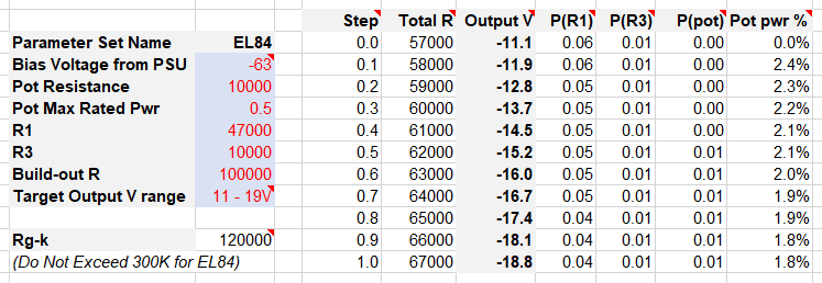
Put in the numbers in the red. Experiment with the values for R1 and R3 and the potentiometer, until you get the desired voltage range in the “Output V” column.
The “Build-Out R” represents the load seen by the preceding driver or phase-splitter stage, so watch the maximum “Rg-k” from the tube’s datasheet isn’t exceeded. In the case of an EL84, that value is 300K. (In the datasheet there will be a specification for this, and it’s diffrent depending on the mode of use of the tube. So look for the “two tubes, class AB” which is in most pentode/tetrode datasheets)
The columns of this spreadsheet:
Step – the setting on the potentiometer
Total R – the total resistance from the bias voltage to ground
Output V – the negative voltage as fed to the control grid
P(R1) – the amount of power dissipated by R1
P(R3) – power dissipated by R3
P(Pot) – the power dissipated by the potentiometer
Pot pwr % – the power dissipated by the pot expressed as a percentage of the pot’s total power rating AND the amount of track being used to conduct.
About Pot pwr % In the specifications for the potentiometer, there will be a power rating. However that power rating is across the entire length of the track. If the pot is set to half-position (assuming it’s a linear taper which in this design it is) then the power handling drops to half. So, this Pot pwr % column shows how much power the pot is dissipating as a percentage of its maximum taking the wiper position into consideration.
Using the circuit Putting all this together, it’s easy to see how it works. Adjust the potentiometer for maximum negative voltage (wiper closest to the left, in this schematic). Power on the circuit and let it stabilize. Measure the voltage across the cathode resistor. Then adjust the potentiometer until the desired current is flowing through the tube.
What is the desired current through the tube? Glad you asked. This depends on the tube itself, and the B+ voltage, and your preference regarding bias.
As a rule of thumb, biasing at around 70% of maximum is the sweet spot with most types when using this conifguration. If you bias low, that’s called “cold” biasing. It means the current through the tube will be low, and the sound may take on a thin, glassy, brittle aesthetic, and the distortion will increase. Bias too hot and you’ll shorten the life of the tubes for no real benefit. 70% is the goldilocks zone. So. Look at the tube’s datasheet. For an EL84 we see the maximum plate dissipation is 12 watts.
70% of 12 watts is 8.4 watts
B+ is 350 Volts
So, using Ohms Law:
we solve for I at 24mA
Across 10 ohms (cathode resistor) our 24mA will give 0.24V
So we want to see 0.24V across the cathode resistor. Adjust the potentiometer until that’s the value shown. Then repeat for the other tube in the circuit, then do a final check that they’re both the same (or as close as you can get)
Please feel free to use my spreadsheet – I developed it to assist in choosing the resistor network values, and also to ensure the power rating of the potentiometer wasn’t being inadvertently exceeded at any setting.