CHOKES - PAGE 3.
Updapted 2017.
This page 3 is about..........

1. General info about choke feed to anodes for input and driver amp stages.

2. Choke with CT for balanced anode Idc feed....
General info on chokes with CT for balanced feed of DC to anodes.
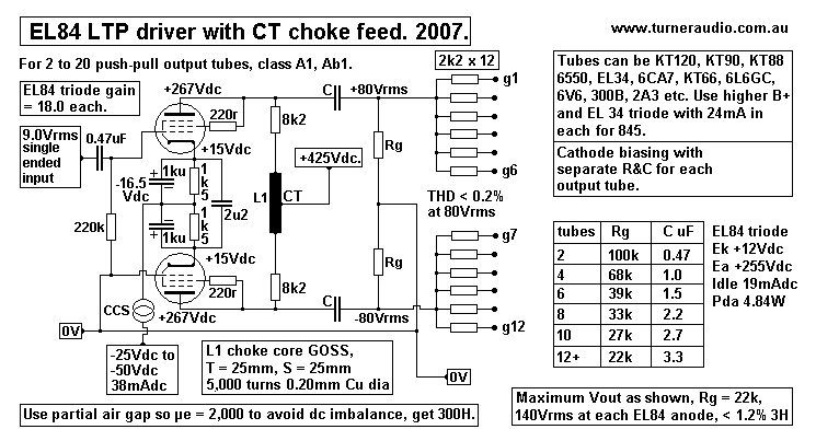
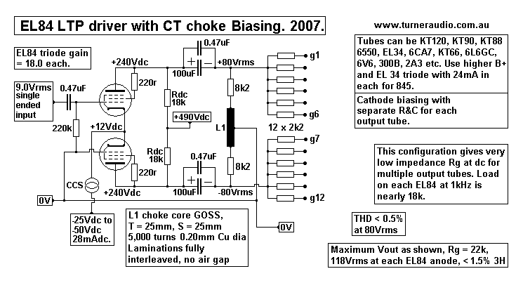
Fig 1. A balanced choke with ct is used for dc supply to a pair of EL84 in an LTP.
Fig 2. A balanced choke with ct is used as the biasing impedance for output tubes.
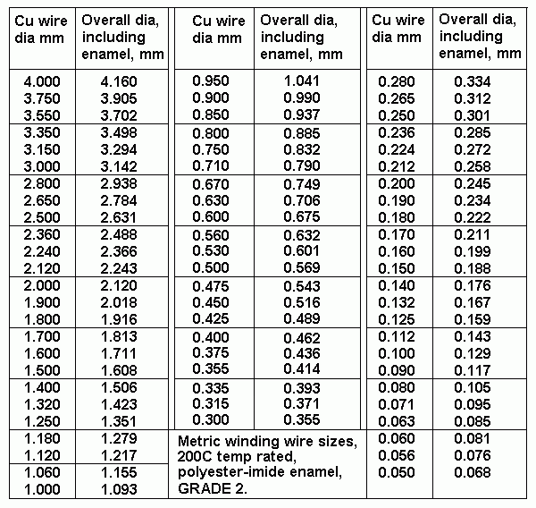
Table 1. wire sizes.
Design Method for Balanced choke for Iac only, Steps (1) to (10).
Table 2. Sizes of E&I cores with 3 different wire sizes.

3. Choke for anode DC feed with Idc and Iac currents....
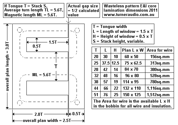
Fig 3. Details of wasteless E&I laminations.
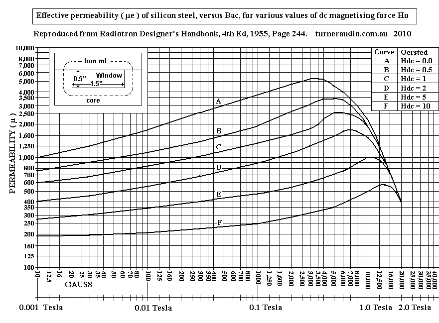
Fig 4. Page 244 from RDH4 re-produced.
Basics about magnetic behavior of current and voltage and coils of wire and iron cores.
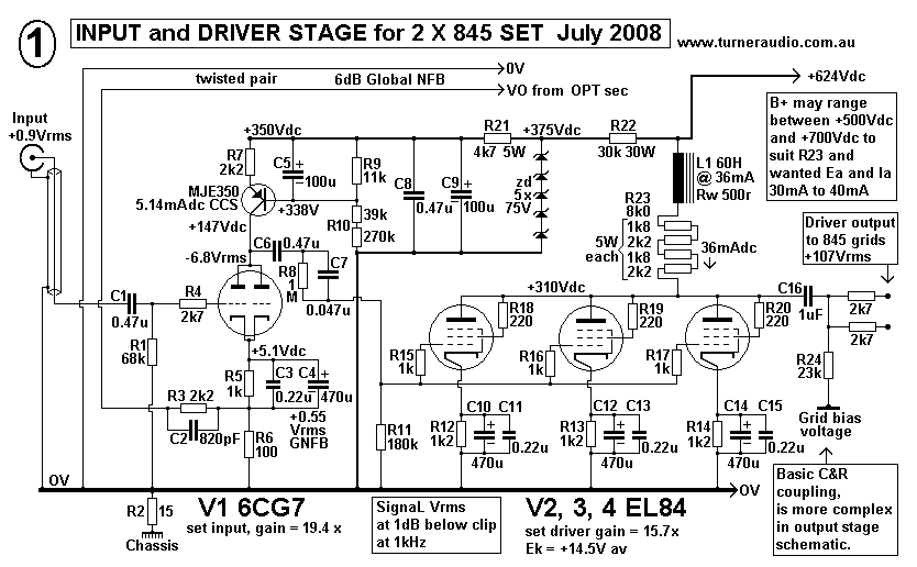
Fig 5. SE Input triode plus SE driver triodes for 55W with 2 x parallel 845.
Design Method for Choke for Iac and Idc, Steps (1) to (14), with notes about air gapping.

Other related pages :-

For basics about inductance and chokes, inductance test circuit, Comparison of CRCRC filters with CLC filters,
Choke Design Method for CLC filter, go to Chokes 1

For about "choke input" or LC filters, Choke Design Method for LC, go to Chokes 2
--------------------------------------------------------------------------------------------------------------------------
1. Chokes for Idc feed - general info.
Chokes can be effectively used to feed dc current to a tube anode so that the anode Vdc voltage remains
stable because choke impedance at very low frequencies is little more than the winding wire resistance.
But as frequencies rise above 0.0Hz the choke impedance rises at a rate of 6dB/octave until a peak is reached
somewhere between 2kHz and 30kHz depending on how much shunt capacitance exists within the choke and
between the two input terminals.
The low winding resistance allows more DC current flow than using a resistor between the B+ supply rail.
The choke feed to an anode offers similar benefits to triode operation as do active constant current sources
to raise the total value of anode load ohms and allow maximum triode voltage gain and minimum distortion.
With a choke, the B+ rail does not need to be as high as with a resistance dc feed or CCS dc feed to anode
because the choke allows the anode signal voltage to swing higher than the B+ rail.

Because a choke has high reactance much higher than any resistance DC feed at audio F between 20Hz
and 20kHz, the signal voltage swing across the choke does not cause high anode current change so the
choke does not consume much audio power and there is more available power to following capacitor
coupled loads such as a volume potentiometer or grid bias resistors of output tubes. Cost and weight
and chassis space usually prohibit "choke loading" in all mass marketed amps designed by accountants.

If you know what you are doing, the choke works magic, and gives excellent sound.

There are some fanatics I know who do all they can to get rid of capacitors and resistances throughout their
audio circuits. I wish them well, but they have made their lives difficult, and in many cases made the sound
worse because so often they are not very well educated about basic electronics.
For them, magnetic coupling through transformers is the only sure way to hi-fi nirvana. Before reliable resistors
and capacitors were made cheaply in the 1930s, transformer coupling was commonly used between stages,
but alas, the quality of them was awful and sound was poor.

"Blocking caps" aka anode to grid coupling caps and resistors do not block fine music flowing through an
amplifier. The main technical problem associated with choke loading or transformer loading of intermediate
amplifier stages is to obtain wide bandwidth and a flat response. It never has been easy to make wide
bandwidth inter-stage coupling transformers and in 1935 those available were very poor, causing high
iron related distortion, bandwidth limiting, and lot of phase shift which prevented only a tiny amount of global
negative feedback if any.
Such phase shifts with NFB may cause LF and HF oscillations which may be difficult to prevent unless the
amp designer has a very good working knowledge about open loop gain shelving and compensation LCR
networks. Even with the best modern design and materials, transformer coupling between stages is a problem
with NFB is applied if not enough knowledge is employed.
I have never needed to make any amp with an IST. However, one would be an idiot to judge choke loading
or choke feed as one judges the IST.

Therefore there is no IST design information with examples at this website.

Chokes are most often used to filter the B+ supply in a CLC low pass filter for dc for anodes of an output stage.
Sometimes a choke is used between triode anode and B+ for low Z source for Idc driver stages, but with high
Z loading for the AF. The best triodes for this are triode strapped EL84, EL86, EL34, and real triodes like ECC99,
6SN7, 6CG7, 12BH7, 6BL7, 45, 2A3. All these and a few others have low Ra, and iron distortion is minimized
with low source Z.
Choke feed for high µ triodes with high Ra and pentodes with even higher Ra dose not work well because the
F response and gain is affected by the choke L and C reactance which varies.

For good input triode performance for a power amp, I will parallel both triodes in one 6CG7 / 12AU7 and use
a transistor MJE350 CCS for 8mAdc, from B+ = +280Vdc, with Ea at 140Vdc. There is huge Vac headroom,
and much less THD than if I had a dc feed R = 18k.

But I could also use a choke of 100H plus a series resistance of 18k, and then loading is a minimum of 18k
at very low F, and rises to 32k at 50Hz, and to more than 500k at 1kHz. The choke shunt might be 300pF, so
choke XC reduces to 53k at 10kHz. Therefore the choke much reduces the Ia change for most of the AF
band and reduces THD. But the transistor CCS does a better job more cheaply. Input tubes generate a tiny
amount of THD even with R feed for Idc.
 
The choke feed becomes justifiable for SE and PP driver stages where triodes have to make up to 150Vrms
to drive an output stage.

All iron wound choke feeds (and IST) create iron caused distortion due to iron hysteresis. This makes the
inductive reactance of the iron cored coil vary for different voltage levels of of any Vac wave. It is most
evident at LF below 100Hz, where the iron cored coil has lower XL around the xero crossing point but higher
XL at high Vac. The HD produced is mainly 3H in PP circuits but can be 3H + 2H for SE triode with choke feed.
Having triodes with low Ra driving such iron cored items reduces the iron caused HD because the Ra is lower
than the variable choke reactance which is parallel to the Ra. However, using a resistance between anode
and choke, usually at least 2 x Ra further reduces the HD from choke at the triode anode.

Iron caused distortion may be high even if the core is GOSS and air gapped. For such chokes, it may be best
to use 50% nickel cores, or mu-metal, but most people cannot find a place which sells such exotic core material.

2. Choke with CT for balanced anode DC feed....
In many of the amps I sold, I used CFB windings on OPT which increased Vac needed for output tube grids
as in the 8585 .
In the 8585, I supply DC to anodes via a choke with CT with fully interleaved E&I laminations with no air gap
and T25mm x S10mm core Afe. N = 8,000 turns of 0.15mm Cu dia wire with a CT.
L max = 720H which gave XL above 1M0 at 1kHz at high Va-a levels. XL = 100k at 22Hz and 20kHz.
At very low Va the XL became lower, but was still much higher than Ra-a = 4k4 for the pair of EL84 triodes,
The Rdc for each EL84 = 8k2, isolating effects of L and Csh at very LF and HF.
For most of the AF band the choke + Rdc allows EL84 pair to work with much higher RLa-a so the THD is
much reduced. The sound was certainly fabulous. The choke with CT is a 'balanced choke' and acts like a
primary of a PP OPT which has no load across it. I found Idc balance remained good, so there was no need
for an air gap.
The 8585 needs up to 80Vrms in two phases to output tube grids. THD from the pair of EL84 < 0.5% at 100Vrms
at each anode.
Where Idc feed is via a resistance Rdc, its value should be at least greater than 10 x Ra so that Ia change in Rdc
is minimized to get lowest THD. To get the wanted high Idc and high Ea, a very high B+ rail must be created.
The choke feed + Rdc allows lower B+ rail and Va may swing positively above B+.
However, the use of high B+ with only Rdc feed is OK if well done, or where there is a convenient high B+ to
use, such as in a pair of 1995 Ming-Da amps I totally re-engineered. The Ming-Da had a pair of 300B with
only 6mAdc to each anode in a balanced driver stage to drive PP 845 for 85W class AB1. Choke feed with Rdc
would have been better.

The main benefit for L + Rdc is that the C coupled following grid bias resistance of output tubes can be much
lower than normally used which helps maintain the grid bias Vdc, especially as tubes age where grids begin to
develop a more positive Vdc than the source for bias Vdc. The Rg for most large output tubes stages needs
to be less than 100k for each output tube because of grids becoming slightly positive because of current in Rg.
The lower value Rg bias resistors make load for driver tubes which is much higher than the total of normally
used Rdc // Rg where Rg usually should be 4 x Rdc value. 
The balanced choke feed was also used in a pair of 300W amps I made.
The basic schematic is also here...
Fig 1.
schema-driver-ltp-choke-anode-aug07.gif
Fig 1 above shows the choke with centre tapped choke in the anode circuit.
The inductance with 5,000 turns with µ = 5,000 can be 704H, but with partial air gapping the µe = 2,000,
and L = 281H.

Doubling the stack height will double the inductance. GOSS C-cores or E&I lams can have µ up to 17,000
with fully intermeshed lams, but if there is a small Ia imbalance of only a few mA dc in the pair of EL84, then
core can become dc magnetized and possibly saturate, causing high distortion. To avoid this I show each
EL84 with separate cathode biasing with 1ku+1k5.;

Partial air gapping will lessen the possible effects of Idc imbalance in EL84. C-cores cannot be partially
air gapped because they are either tight together when max µ can be up to 15,000. Air gapping is easier for
C-cores. But for GOSS E&I lams, if all Is are one pile and Es in another, and the two piles are tight together,
max µ would not exceed maybe 1,500. If µ of between 1,500 and say 17,000 max is wanted, the E&I lams can
be assembled in piles of say 5mm high each, then each pile of Is is against each pile of Es, facing East,
and then the next pile of Is+Es faces West, and so on, so for stack of 25mm, there could be 5 piles of Es
and Is facing opposite direction. The resulting µ cannot be guessed or calculated, and the number of piles
tested to get the wanted µ. If each lamination is 0.35mm thick, there would be about 14 lams for each 5mm
pile of Es or Is.
Most people don't bother doing any this, but then I can only say what's best, and if anyone wants to take the
short cut and not use partial air gapping, then they should not complain to me about the distortion if one EL84
has more Idc than the other.

If you don't want to use a CCS with MJE340 transistor then take a resistor from bottom of cathode biasing
R&C networks to a -100Vdc rail, about 3k3 rated for 10W would be OK. Then use a balanced drive to each
EL84 grid from 6CG7 input stage LTP. With balanced drive, the EL84 balanced amp needs about 4.5Vrms
to each grid to give the 80Vrms at each anode, oppositely phased. The two Va from EL84 should be very
well balanced within 1% of each other.

8k2 can be rated for 5W, but could be higher. If an anode shorts to 0V, each 8k2 has 52mAdc, and
heat = 22W. For normal operation, heat = 1.6W. I have never seen an anode short to 0V in a situation like
this.
The typical shunt capacitance in L at each live end to CT might be about 150pF, where both are driven
by the tubes. Ra of each EL84 = 2k2 and with the lowest expected Rg load of 22k, there is 2k0 + 8k2 = 10k2
in series with 150pF to 0V, giving HF pole at choke = 104kHz, and this shows the HF bandwidth at EL84
anodes will not be much affected by choke self capacitance. 12 output triodes could each have 30pF input C
for total of 360pF, which then is fed by 2k0, so HF pole = 220kHz, and this is quite OK.
The big benefit of using EL84 in triode is that it can do the work of about 3 paralleled 6SN7.

Below 20Hz, the choke reactance falls to zero at DC, but the EL84 have 8k2 minimum load, So the HF AND
LF will be well extended, and the 8k2 will isolate choke L and C from having much effect on gain, and there will
be no extra phase shifts which will allow GNFB. What slight reduction of gain occurs below 40Hz and above
50kHz is a shelved response and entirely benign.

Fig 2.
schema-driver-ltp-choke-biasing-aug07.GIF
Fig 2 schematic has the choke with CT and 2 x 8k2 used for biasing the output grids to obtain a very low biasing
resistance at very low F. The 2 x EL84 can be set up without much regard for Idc imbalance causing choke saturation
because 2 x 18k are used for Idc to each EL84 anode, and there is no Idc in the choke because of the coupling caps.
The loading of the tubes is much lower at all times than in Fig 1. At 1kHz, the choke has very high XL and load may
be neglected. Total RLa = 18k // 22k = 9k9, where there could be many output tubes. Va with Ia 14mAdc could be
about 97Vrms and quite enough, but THD will be higher than for Fig 1.
I never saw any reason to use such a scheme as in Fig 2.

2. Design Method, - Choke for ac only, for Fig 1.

(1) Choose series R between anodes and ends of winding to be at least from 3 x Ra to 5 x Ra of tube.

Tube = EL84 triode, Ra at 19mAdc = 2k2. Series Rdc for Fig 1 = 8k2 to suit available B+ and wanted Idc.

(2) Consider each EL84 operating Vac and Iac conditions, Fig1.
B+ = 425Vdc, less +12Vdc for Ek = +413Vdc. Ea = 255Vdc, idle Ia = 19mAdc, Pda = 4.9W = OK.
DC RLa = choke Rw 200r + 8k2 = 8k4. Loadline analysis will show following :-
With XL = 0.0r at DC, and no Rg load, Ea = 290Vdc approx, and Idc = 19mAdc. Va max could be 108Vrms.
This condition at 0.0Hz will change where F rises.
Where L = 280H, XL at 20Hz = 35k2. The choke load at each anode = 17k6.
So at 20Hz, XL 17k2 in series with 8k2 = 19k3. With Rg load = 22k, total RLa = 10k0 approx.
Max Va swing = +/-175Vpk = 123Vrms.
There will be 80Vrms available at less than 20Hz where there is little energy with most music.
For all F well above 20Hz, the choke XL increases so that it ceases to load the EL84 very much and by say
500Hz, RLa total = 20k, and Va max available increases to 136Vrms.
The maximum Va with no Rg load and at 500Hz = 148Vrms.

(3) Are there two Idc flows to be balanced?
Yes, there are two equal Idc flows in opposite directions for each 1/2 winding.
Therefore allow for partial air gap for E&I lams with µe max < 2,000.
Use R+C cathode biasing.
NOTE. If you answered No, it means the choke has NO Idc flow at all, then µe may be as high
as maximum possible and core will have no air gap, which suits Fig 2 circuit.

(4) What is worst fault condition? If EL84 anode shorted to 0V, then Idc = B+ / 8k2 + Rw.
1/2 choke Rw = 200r approx, so Idc max = 425Vdc / 8k4 = 51mAdc.

(5) Apply safety factor of 2.0 to Idc value calculated in (4), to get Idc wire rating.
2.0 x 51mA dc = 102mAdc.

(6) Calculate theoretical wire size able to survive a tube fault condition with 3A/sq.mm max.
Wire Cu dia = 0.65 x square root Idc = 0.65 x sq.rt 0.101A = 0.206mm.
Cu dia in mm, 0.65 is a constant for all equations, Idc in Amps.

(7) Select nearest wire size available from table......

Table 1.
table-wire-sizes.GIF
Table says 0.212mm nearest, but is not available. Use Cu dia = 0.200mm, = 0.245mm o/a dia including enamel.

(8) Calculate choke inductance.
Choke should give XL > 10 x Ra-a at 20Hz. Ra-a = 4k4, so XL > 44k at 20Hz,
L = XL / ( 6.28 x F ) = 44,000 / ( 6.28 x 20 ) = 350H.

(9) Choose Wasteless E&I core T x S dimensions from Table 2 for 4 different
T sizes of core with 3 different wire sizes from Table 2 :-
Table 2.
1
2
3
4
5
6
Wasteless E&I Square Afe,
T mm x S mm
Core window e
L mm x H mm
Bobbin winding area
L mm x H mm
Turns 0.15mm Cu dia, oad 0.188mm
L in Henry
µe = 2,000
Turns 0.20mm Cu dia, oad 0.245mm
L in Henry
µe = 2,000
Turns 0.25mm Cu dia, oad 0.301mm
L in Henry
µe = 2,000
25mm x 25mm
37.5 x 12.5
33 x 9.5 = 313sq.mm
8,000t
720H
5,000t
281H
3,000t
101H
28mm x 28mm
42 x 14
38 x 10 =  380sq.mm
10,000t
1,260H
6,000t
453H
4,000t
201H
32mm x 32mm
48 x 16
44 x 12 = 528sq.mm
14,000t
2,822H
8,000t
921H
5,200t
389H
38mm x 38mm
57 x 19
52 x 15 = 780sq.mm
20,000
6,840H
11,500t
2,261H
8,000t
1,094H
Examine column No 5 for wire size from step (7), wire Cu size = 0.2mm.
Search for nearest Inductance below value calculated in step (8)

Choose T x S = 25mm x 25mm, core window 37.5mm x 12.5mm, N = 5,000 turns, L = 281H.

NOTE. Inductance and XL is directly proportional to stack height S.

Increase stack height S for selected core to increase L to wanted value in step (8)
Revised S = 25mm x wanted L / L in table 2,
= 25mm x 350 / 281 =  31.14 mm.

Use bobbin made for T = 25mm, and S = 32mm.

NOTE. With Wasteless E&I lams, the core window area = 0.75 x T squared. If C-cores are used, the core window
area is often much more than 0.75 x T squared, especially if just one C-core is used. For example, one might have
a C-core with window 39mm x 13mm, and strip build up or T = 12mm. If the strip width is 25mm, then Afe = 12 x 25.
The window is similar to E&I T25mm, but C-core inductance will be 140H with same 5,000 turns.
One might source a C-core with strip width of 50mm to get the 281H.
Use of 2 C-cores for 00 pattern will give 281H.

C-cores have maximum µ of about 12,000 with well polished cuts in the wound GOSS strip used. The 2 cuts in each
C-core reduce the µ max of 40,000 to 12,000 with C-cores brought tight together with no air gap, so the cuts
act like an air gap. To reduce C-core from say 12,000 to 2,000 requires some plastic sheet between both C-core
cuts of 0.01mm to 0.03mm. Careful measurement of XL and adjustment of air gaps are needed to get the air gap
correct.
To replace T25mm x S25mm E&I lams, two C-cores with window 38mm x 13mm are fine and with build up of 12mm
and strip width 25mm are OK. Use wider strip width to get the equal to having higher stack size.

Whatever is used for a core, you can't compromise the design. Using exotic materials such as nickel laminations,
mu-metal, amorphous etc may seem just fine, but all parameters must be complied with including saturation behavior
with DC offset and / or low frequency saturation.

NOTE. The Inductance calculated so far has been based on performance at maximum Va-a and 20Hz. But µe
will be less at very low signal voltage levels, hence the XL will become lower at low Va-a. This will not affect the
tube operation enough to worry about the slight load ohm reduction at very low Va-a.

Fig 3. An additional diagram of wasteless lamination sizes :-
Wasteless2-E&I-lam-dimensions.GIF

(10) Check Fsat, Bac, Possible Bdc, and operation of the design so far.

Frequency of core saturation, Fsat, with maximum Va-a, and maximum Bac of 1.5Tesla and with no DC magnetization.
Fsat = 22.6 x Vrms x 10,000 / ( Afe x 1.5 x N ) in Hz.
For Va-a = maximum possible with no RL = 2 x 135Vrms,   
Fsat = 22.6 x 270V x 10,000 / ( 32mm x 25mm x 1.5T x 5,000t ) = 10.2Hz.

Is Fsat < 20Hz ? if Yes, design is so far OK.

NOTE. Bac for choke has been worked out for max Va-a 270Vrms applied across the choke. But as F becomes lower
the 350H reactance reduces, and at 10.2Hz, XL = 350H x 6.28 x 10.2Hz = 22.4k. There is 8k2 in series between each
anode and ends of choke winding. The Z between anodes for Z ( XL + 16k4 ) = 27.7k, and with Va-a = 270Vrms,
Iac in L + R = 270V / 27.7k = 9.74mA, and across the choke there is 218Vrms. So in fact, the choke Bac will never
reach max allowed 1.5Tesla above 10.2Hz, and below 10.2Hz, choke XL reduces which lessens the Vac across it and it
will also never have Bac = 1.5Tesla.

Possible Bdc, ie, DC core magnetization can be due to unbalanced Ia in the two tubes.
Assume maximum possible Idc imbalance = 30% of wanted Iadc in one tube of pair.
If one tube tries to conduct 22mA, the other will have Ia reduced to 16mA, to make the total of 38mA from cathode CCS.
Idc unbalanced = 6mAdc, and across 1/2 the turns of choke.

Bdc in Tesla = 12.6 x Idc x N x µe / ( iron ML x 10,000 ) = 12.6 x 0.006A x 2,500 x 2,000 / 140mm x 10,000 ) = 0.27Tesla.
is Bdc < 0.75Tesla? if Yes, design is OK so far.
The increase of THD for the pair of EL84 may not be noticed, but yearly amp servicing would discover the problem.
The difference of Vdc between anodes will be 50Vdc. Normally the difference < 5Vdc.
EL84 are operating in conditions for very long life because idle Pda is less than 1/2 maximum Pda of 12W, and during
my 18 years building and servicing tube amps, I never saw a pair of Russian EL84 have widely different properties over
many years, even without the cathode biasing I show in Fig 1.

If one EL84 ceased all conduction and becomes an open circuit due cracked glass and gas entry, the other EL84 would
have Ia = 38mAdc which will reduce Ea to about 108Vdc. The Bdc would then rise to 1.7Tesla and the choke will be
fully saturated, and there will be no output from the dead EL84, but will be some output from the other. THD will be high.
All owners must keep an eye on their tubes, and detect when one or more has become cold, or has turned a white color
due to gettering becoming oxidized.

NOTE. The choke designed so far has ability to swing Va-a = 270Vrms, much higher than the anticipated maximum of
80Vrms needed in most amps amps with octal tubes. Tubes like 845 need up to about 140Vrms if set up for class AB
with Ea 1,200Vdc and Ia 40mAdc, and Eg1 bias = -190Vdc. But their Rg can be 100k, and its unlikely more than 2 x 845
will ever be used because a PP pair can make a very good sounding 85W.

In amps with McIntosh output stage where there are equal turns used for 50% CFB in anode primaries, Va-k for 6550
may be 274Vrms, so Va = Vk = 137Vrms, opposite phase, so if Vg-k = 30Vrms, then Vg-0V = 167Vrms max.
McIntosh company used 1 balanced and bootstrapped 12BH7 RLdc from OPT to get such Va swings from each 12BH7.
To avoid this slight use of positive FB, a balanced choke can be used with 2 x EL84 triodes or even 2 halves of ECC99.
The anode loads for the balanced amp are high and wide Va swings are possible with higher Ea = 300Vdc, with Ia
in each triode = 12mAdc. 
I never made a PP amp with 50% CFB with McIntosh output stage because I found that no more then 20% CFB was
ever needed, and allowed grid drive to always be less than 85Vrms. Much less NFB was needed than used in McIntosh
amps. 
----------------------------------------------------------------------------------------------------------------------------

Basics about iron cored chokes and OPT cores with Idc in one direction and with Iac.
Fig 4.
graph-GOSS-core-permeability.gif
Fig 4 above is a reproduction of the curves for GOSS made in 1955 and as shown in the Radiotron Designer's
Handbook, 4th Ed, 1955, Page 244. The curves A to F give permeability for GOSS laminations at various amounts
of DC magnetization depending on turns and Idc flow between zero Idc for curve A, to heavy Idc for curve F.

A sample core was used to get the above graph established, and is see at top left, and was a C&I laminated core,
ie a C plus I with two magnetic gaps like E&I.

The window size = 0.5" x 1.5" with iron magnetic path length ML = 5.57", plan size 2.5" x 1.5". 
Metric sizes, window = 12.7mm x 38.1mm, ML = 141.5mm, 63.5mm x 38.1mm. The Stack height and turns on
the core shown are entirely missing, so it is difficult to understand this famous brave effort of a graph about
magnetism by a zealous company employee who probably didn't give a stuff if he confused all readers for
the next 70 years.

I make no apologies for the basic concepts here which are 120% certain to confuse nearly everyone in 2017 who
cannot think, and who depend on Google and a mobile phone. The study of electro magnetic phenomena and
descriptions of magnetic coil properties and behavior involve magnetic study language which has evolved over
about the last 200 years. The concepts were defined and described mathematically, which set off allergic
reactions in some people. Letters of the alphabet are used to nominate the concepts and mathematical
quantities. Googling anything about magnetism such as exactly how to calculate an air gap leads to a whole
pile of people re-gurgitating magnetic knowledge without them explaining anything, or telling us how to set an
air gap.
 
First thing to think about is magneto motive force, MMF, known simply as F, except that confuses is with F
for frequency. Regardless whether there is Iac or Idc in a coil, or both, frequency is not essential to consider
with MMF which is Number of Turns x Current. So F = N x I, current in Amps. It is the amps x turns which
give rise to the magnetic field, which is put to work in 1,001 ways.

Second is the magnetic field, H, which exists within the coil inner area where it is most strong, for a given
length of magnetic path. The magnetic field per length is sometimes stated as H = N turns x Amps / Meter.
The H unit in RDH4 is called the Oersted, after a Mr Oersted. Most units of magnetism are named after
fellows who were fascinated by electricity and magnetism, and who became famous for their discoveries,
Ampere, Volt, Oersted, Maxwell, Lorentz, Gilbert, Tesla, and I suggest you search on each via google
because the history of discovery is a path to understanding if you don't become immediately bamboozled
and hypnotized whenever someone says slowly e-l-e-c-t-r-o-m-a-g-n-e-t-i-s-m  :-O

1.0 Oersted, Oe, is the magnetic field along the centerline of an infinitely long solenoid coil of wire where
1.0 Amp flows in wire, and where we select a 1.0 meter long portion of the coil, and where there are 79.6
turns within the 1 meter coil length. So 1.0 Oe = 79.6Amp-turns per meter of magnetic path length.
There are 39.47 inches in a meter, so 1.0 Oe could also be 2.016At/inch. There is a reason why Mr Oersted
decided on 79.6At/M, rather than some other number, but then I have not read everything Mr Oertsted ever
wrote.

If you have a toroidal winding where all the turns of wire are wound all around the toroid "circle" then you
have a magnetic path equal to the circumference, and magnetic field inside the coil will be similar to an
infinitely long solenoid. To avoid infinity, just bend the solenoid around into a circle, and you have a toroid.
Where there is an iron toroidal core within the turns, the magnetic path length ML is the average
circumference of the iron, even if the turns do not extend all around the toroid.

If you put turns around a bobbin and insert and iron core such as E&I or C-cores the ML is all around the
iron, ie, is around each window in the core. The iron core has an equal magnetic field all around its ML,
even if there are many layers of turns along only about 1/3 of the ML.

The addition of an air gap can change H value of At/M because the air gap effectively increases the ML.
So the ML becomes the sum of iron ML plus Air ML, and the effective total ML can be longer than the iron
ML on its own.

One might assume H for a bar core or no core at all will be N x I / coil length. One could use a stack of
Is to make a bar say 63mm long and have a coil along say 33mm of that bar, but the ML is all along the
bar, plus all around the outside of the coil in the air, and that is much longer than the bar core length.
The L with bar core will only be about 4 times the same L with no core.  
Where the sample core in Fig 4 is used, ML = 142mm. So H = N x I / 0.142meters.
This probably makes no sense now, because the use for H cannot yet be seen......

Third. Permeability, µ. This is just a magnetic number, no units, but in any coil the material in its core and
way it is arranged much affects the magnetic field strength obtained by a given number of turns and amps.
In a vacuum and with no iron, µ = 1.0, and is virtually the same number in air, for an air cored coil.
When a GOSS core is used instead of air, the magnetic field strength can increase by up to say 40,000
and the coil can become useful for transformers and electric motors etc. A primitive simple bar core for
a give coil using carpenter's nails will give µ = 4. This makes a usable choke but inductance s only 4 times
above what is possible for the same coil with an air core, and magnetic properties of pure iron isn't wonderful.
So there can be huge variation of µ depending on core type, material, and if any air gap is used within the
magnetic circuit loop.

For a spiral wound GOSS core, µ can be up to 40,000, up to 15,000 for some E&I lams or C-cores.
B max can be 1.6Telsla. For cheaper medium grade transformer Fe-Si cores with less rolling and heat
treatments B max can be from 1.2Tesla to 1.4Tesla. Distortion at LF is much more than in GOSS.
Max µ can be from 2,500 to 3,500, which is still quite enough for any OPT. The low grade iron does produce
more THD in an audio amp but with a larger core than GOSS, the THD is less than produced by the tubes.
Core heating loss in lo grade cores is not a problem because average B is much less than in a 50Hz mains
transformer operating near its B max.

The ML can vary between the toroid circumference or around the Es and Is or be effectively much longer if
a small air gap is placed along the iron ML.
Toroidal cores for air gapped chokes and SE OPT are rarely made except by those who take extra effort to
make them, and they are expensive, from Pliotron.
C-cores are usually always GOSS with thin lams glued together. They make excellent chokes and have
µ max of 12,000 with the cuts well polished. Some GOSS E&I lams also give similar high µ when fully
intermeshed. Bobbins are easy to wind and air gaps are easy to adjust with C-cores or E&I.

The µ permeability of all Fe-Si core material varies with level of Vac, frequency, and with level of Idc.
So the term µ is vague until the Vac and Iadc conditions and air gap are specified.
The µ quoted for a given core material is the maximum possible for that type of core.

In 1955, when RDH4 was published, commonly used E&I GOSS cores had maximum µ = 5,200, made by
Ludlum, as the basis for the above Fig 4 graph above. Other companies may have got higher µ for GOSS.
But most engineers thought 5,000 was just fine for OPTs, PTs and chokes.

The air gap increases the effective ML = MLe = [ iron ML + ( µ x air gap ) ]. If ML = 142mm,
and max µ = 5,000, air gap = 0.5mm, then MLe = [ 142mm + 5,000 x 0.5mm ] = 2,642mm.
The increase of magnetic ML = 2642 / 142 = x 18.606.
But in equations for a choke with an air gap, the increased ML is not used, and instead the reduced µ
is used, and it is called effective µ, ie, µe. In this example, µe = 5,000 / 18.606 = 268.7.

For any air gapped core, µe = iron ML x µ / [ ( µ x ag ) + ML ]

Therefore Air gap ag = ML x ( µ - µe ) / ( µ x ue ).

These formulas are correct enough for C-cores because the µ is for core with no gap material where the
cuts are tight together.
But for E&I, the u is for maximal intermeshing of Es and Is. If all Is and Es are in two piles and held tight together
with no air gap the max µ may be about 1/4 of the µ with maximum intermeshing. On average, for GOSS E&I,
max µ for close butted Es and Is = 1,000. this is because grain direction between Es and Is arranged this way
changes 90 degrees, and the close butt is equivalent to longer ML, or same as having an air gap, when there is
actually none. So for E&I lams the air gap should be calculated with µ value being 1/4 of the max µ that you
measure with maximum intermeshing.
 
In E&I and in double C-cores, there are two loops around each window so gap material is always
0.5 x calculated gap size. Air is never used for the gap, but usually it is non magnetic material such as
plastic sheet or electrical paper. Ordinary paper is OK if it is soaked in vanish or resin, and found to not
compress after assembly before the yokes holding Es to Is are tightened.

µ = B / H where B is the magnetic field density in Gauss lines of magnetic force or Tesla over a given
sectional area across the magnetic field. Expanding the formula, µ = B / ( N x I / ML ) = µ x ML / ( N x I ),
where B is in Gauss  N is turns, I is Amps, ML is magnetic length, and I don't know what units they are,
and constants are missing from the equations to make them work with inches or millimeters or Tesla
instead of Gauss, but how one thing affects the other is well described mathematically.

From above, B = N x I x µ / ML.
Using an air gap would have B = N x I x µ / [ iron ML + ( µ x air gap ) ]. The divisor
is MLe, effective longer ML with air gap, and there is no need to calculate µe.
But instead, the text book equations use B = N x I x µe / ML so first the µe needs to be known, or calculated
if the core µ is known and the air gap size.

For real world calculations, Bdc in Tesla = 12.6 x N x Idc x µe / ( 10,000 x ML ). 12.6 and 10,000 are
constants to allow Tesla and ML in mm.
Notice the equation has the included factor = µe / ML. For un-gapped core it would be µ / ML.
But where an air gap exists, MLe = [ iron ML + ( µ x air gap ) ].
For ML = 142mm, and air gap = 0.5mm, µ = 5,000, MLe = 2,642mm. The factor µ / ML will then become
5,000 / 2,642 = 1.8925. Above the µe was calculated = 268.7, and ue / ML factor = 268.7 / 142 = 1.8922,
so now you all know there is nothing wrong with the equations.

I do not know how Gauss found the size of a magnetic line of force, but 1 Gauss is a feeble amount of
magnetic field. I do not know how many Gauss are in the average magnetic field at the surface of Earth.
Google will tell you. But it is strong enough to swing a small needle in a hand held compass to allow us
to confirm in our minds that we are certainly quite lost when we have gone bush-walking somewhere
without a Sat-Nav device. Nevertheless, before Sat Nav, people used paper maps and a compass to
estimate where they were, and in what direction they had to go, and hopefully, they wouldn't find they'd
spent a day walking in a big circle. The little pointer has been permanently magnetized and its end marked
N always points north. Earth's field pushes the pointer one way with a small force.
Someone decided that if you have 10,000 Gauss, you can give them all the same name and call them
all 1 Tesla. With this amount of magnetic force, many things can happen in electric motors and generators.
So B = µ x H, and for an air cored coil µ = 1.0, so B = H.
Expanding the formula, B = µ x N x Amps / ML, and where µ is air, and = 1.0, B = N x Amps / ML.

B = field strength density, and can be Bdc for the unchanging field strength due to Idc current in a coil.
B can be Bac for where field strength density changes due to Vac and Iac change at a coil.
Both Bdc and Bac can exist together, so that a core could have Bdc = 0.7Tesla, and Bac = 0.7Tesla,
and the total Bdc + Bac = 1.4Tesla. If Bdc is established, and Vac applied across the coil, the range of
total B change is from 0.7Tesla in one direction to 0.0Tesla, and from 0.7Tesla to 1.4Tesla in the same direction.
Further increase of Bdc beyond 1.4Tesla may cause saturation and high distortion currents so Bac is limited to
0.7Tesla.
If no Idc was present, then core could move to 1.4Tesla in either direction, and Bac can be 1.4T, and the applied
Vac across the coil is twice that for where Bdc = 0.7Tesla.

SE OPT or chokes with Idc have core magnetization due to both Idc plus Iac.

The calculations of Bdc and Bac and air gap is what becomes critical for
designing chokes with both AC + DC present.

The higher the Idc becomes, the lower the µe must become for a choke to avoid core saturation from Idc while
allowing enough Bac change "headroom" for audio Vac applied across the choke without causing saturation at
low frequencies. The µe must be high enough to get a high enough amount of inductance. 
---------------------------------------------------------------------------------------------------------------------------------
Example of a choke with Iac and Idc :-

Here is the driver stage for driving a pair of SE 845 in parallel to make 55W of pure class A.
Fig 5.
845set-jul08-1-schem-input-driver.GIF
V1 is a paralleled 6CG7, and has 5.14mA Idc feed to anode through MJE350 which works to give effective
collector resistance at audio F > 5M0, and with shunt C < 100pF. So MJE350 acts like a very nearly constant
current source, CCS. So the anode load experienced by V1 is R11, 180k which is Rg to bias the 3 following
EL84. The paralleled 6CG7 anode Ra = 7k0 approx and so total anode load = 26 x Ra, so THD is negligible.

There is nothing to be gained by using a choke to feed Idc to V1 so I don't have a design recipe here for one.
Any is free to design a choke using general principles below. I can offer a wild guess, use RLdc = 39k 5W in
series with choke with L = 150H. XL = 39k at 41Hz. At 410Hz, XL + 39k = 392k, and THD is low.

V2, 3, 4, are 3 paralleled EL84 in triode giving Ra = 700r where idle Ia in each = 12mAdc. Choke L1 has air
gapped wasteless E&I GOSS laminations with 5,000 turns of 0.2mm dia wire on a core with T = 25mm, S = 32mm,
but S could be 38mm or 50mm. The gap was set to give approximately for 60H at 36mA, and keep Bac and Bdc
within good limits of operation. 
XL 60H at 20Hz = 7k5. At 20Hz, and added series R = 8k0, so R+L resultant load = 11k. approx.
This 11k is in parallel with capacitor coupled bias resistance of 23k0 for 2 x 845, so final total load becomes 7k7.
At 20Hz, total RLa = more than 10 x Ra, so THD is low even at 107Vrms. The THD is nearly all 2H which
cancels some of the 2H produced in the 845 SE output stage and at low levels the amp produces similar low
THD compared to a good PP amp of the same power. The maximum drive voltage needed for class A1 SE 845
in the SE55 is 107Vrms, but the driver stage should be able to produce 1.5 times more Vac so that THD is lower
at the wanted Vac levels. At 100Hz the XL increases to 37k, and total load on EL84 triodes rises from 7k7 at 20Hz
to above 15k, and RL > 20 x Ra, so THD is low. The increasing XL with higher F means that for most audio
F the loading is close to 21k.

Unlike PSU filter chokes, the choke feed with large Vac has quite low Iac and there is no need for low Rw as long
as the wire can survive excessive Idc if tube anodes short to ground and the RLdc in series with choke carries
nearly all the heat generated by Idc.
Idc density should not exceed 3Amps/sq.mm even in if idle Idc is doubled. The ac current can be neglected
because Vac increases and decreases Ia by the same amount, so the Iac does not add to the total I in the coil.
RLdc = R23, 8k0, and rated for 20W.
If anode connection to bottom of R23 became shorted to 0V, there is 645n
if the anode connection went to 0V, there is +624Vdc across total R = 8k0 + Rw choke 500r so I = 73mAdc.
This is about twice the normal idle I = 36mAdc. The heat in choke with 73mAdc = 2.7W so it survives. Heat in R23
= 43W, so expect one R of the 4 in R23 to fuse open. this will not cost much to replace, but the choke would cost
a huge sum. There is nothing to stop anyone using aluminium clad resistors screwed to the chassis and with a total
50W rating.
----------------------------------------------------------------------------------------------------------------------------------------------------------
Design steps for L1 in Fig 5 above :-
(1) Choose series R between anodes and end of winding = 5 x Ra to 12 x Ra of tube or parallel tubes.

Tubes = 3 x EL84 triode. Ra of each = 2k1 approx with Ia = 12mA in each. Ra of 3 in parallel = 700r.
Series R could range between 3k8 to 8k2, depending on available B+.
B+ for a driver stage with choke should be at least 1.5 x Ea. Fig 5 shows B+ = +624Vdc, about 2 x Ea, OK.

Fig 5 shows R23 = 8k0. Vdc across 8k0 = 8k0 x 36mA = 280Vdc, idle Pd = 10.4W. Allow Rw = 500r.
If tubes become short circuit, max Idc in 8k0 = 624V / 8k5 = 73mA, so wire of choke must not fuse open
with Idc = 73mAdc. A convenient fuse in series with choke and B+ would be for 100mA, slow blow,
so wire should be rated for 100mAdc, at current density = 3A/sq.mm.

(2) Calculate theoretical wire size able to survive highest Ia expected = 120mAdc to blow fuse.
Cu dia wire = 0.65 x square root Idc = 0.65 x sq.rt 0.12A = 0.225mm. 0.65 is a constant for all equations,
Idc is Amps.
From wire table, try Cu dia = 0.2mm = 0.245mm oa dia. Max continuous Idc at 3A/sq.mm = 94mA, and choke
will survive 120mAdc until fuse blows.
Table 1 repeated.
table-wire-sizes.GIF
(3) Go to table 2 showing wasteless E&I core sizes and possible turns, see column 5 for 0.2Cu dia wire with
0.245mm oa dia giving 5,000t on core with T25mm, L = 37mm x H =12.5mm.
The inductance with no air gap = 281H, but this can be reduced with air gap for Bdc < 0.6Tesla.

(4) Calculate initial minimum XL wanted = 10 x Ra = 10 x 700r = 7,000r, at 14Hz.
Calculate L = 7,000r / ( 6.28 x 14Hz ) = 80H.

(5) Calculate µe, effective core permeability, µe, and allow max Bdc = 0.6Tesla.
µe = Bdc x 10,000 x Iron ML / ( 12.6 x N x Idc )

Wasteless pattern ML T = 25mm = 5.6 x T = 142mm, Idc = 36mA, N = 5,000t,

Required µe = 0.6 x 10,000 x 142 / ( 12.6 x 5,000 x 0.036 ) = 375.

(6) Calculate Stack for 80H and ue = 375.
Lp = 1.26 x N squared x Tmm x Smm x µe / ( 1,000,000,000 x ML ).
Smm = Lp x 1,000,000,000 x ML / ( 1.26 x N squared x Tmm x µe )

For this choke, Smm = 80H x 1,000,000,000 x 142mm / ( 1.26 x 5,000 squared x 25 x 375 ) = 38.5mm.
Use bobbin for T25mm x S38mm.

(7) Calculate Fsat for Bac = 0.6T, Vac = 160Vrms.
Fsat = 22.6 x Vac x 10,000 / ( Afe x N x Bac )

For this choke, Fsat = 22.6 x 160Vac x 10,000 / ( 25mm x 38mm x 5,000t x 0.6T ) = 12.6Hz.

Is this below 14Hz? Yes, so proceed. If No, try making Stack higher.

(8) Analysis. Calculate F where XL = R23 8k0 + Rw.
F = 8,500r / ( 6.28 x 80H ) = 17Hz.
Calculate Total RLa at 16.9Hz. Z ( XL + 8k0 + Rw ) = 8,500 x 1.414 = 12k0.
Z ( Rg 23k + Xc 1uF ) = 32.5k. Total RLa = 32.5 // 12k0 = 9k0 approx.
Loadline analysis tells me max Va for RLa = 9k0 =173Vrms.
Wanted max = 160Vrms, OK.
With 160Vrms at anode, and at 17Hz, there is 113Vrms across L and also across R23 8k0.

Bac in choke at 17Hz = 22.6 x 113V x 10,000 / ( 25mm x 38mm x 5,000t x 17Hz ) = 0.31Tesla.

Conclusion :-
For a constant Va = 160Vrms, as F becomes lower, the XL reduces, so Vac across L reduces and Bac will never
become higher than 0.6Tesla, so core will never saturate below 17Hz. As F rises above 17Hz, the XL increases
so higher Vac is across L. But Bac will never reach 0.6T because of effect of series R23 8k0.

(9) Many people wanting to make a choke will already have some core material taken from some old transformer.
They will make a bobbin easily, and only need to purchase the right size of NEW wire. Calculations for an alternative
choke will depend on all the many variables I have nominated so far. For this choke here, Afe = 25mm x 38mm
= 950sq.mm. Tongue could be 32mm, Stack 32mm for Afe = 1,024sq.mm. The wire size can stay the same, for
the same 36mAdc. Table 2 shows turns = 8,000. It should work well.

(10) Calculate Theoretical air gap and gap material thickness.

Air gap, ag = ML x ( µ - µe ) / ( µe x µ ) Where air gap ag is the total gap in mm consisting of two gaps each
0.5 x calculated air gap size. Gaps are filled with non magnetic sheeting within the iron magnetic path, ML.
µe is effective permeability with air gap, µ is the maximum possible permeability.

For GOSS C-cores, when no gap exists and cores are tight together, µ max may be say 12,000. Introducing an air
gap no matter how small will follow above formula where µ = 12,000.
For GOSS E&I lams, when all Es and Is are maximally intermeshed, µ can be up to maybe 15,000 but when all
Is and Es are in two separate piles, then brought tightly together without an air gap, then µ will be much less than
15,000 and be about 1,500 maximum. Unlike C-cores, the grain direction of Is is at 90degrees to Es and despite
there being no air gap, the iron behaves as though there was an air gap.
For the equation above, for GOSS E&I, allow µ = 1,500.

For GOSS E&I choke T255mm x S50mm, I = 36mAdc, µe = 375, ML = 142mm,
Ag = 142mm x ( 1,500 - 375 ) / ( 375 x 1,500 ) = 0.284mm. Use gap material = 0.142mm.

If this choke had GOSS C-cores, then higher µ = 15,000 for C-cores will be used if the iron ML is the same as for E&I.
For GOSS C-cores, µ max = 15,000, Ag = 142mm x ( 15,000 - 375 ) / 375 x 15,000 ) = 0.369mm. Gap material = 0.185mm.

The gap size must be confirmed with choke in the circuit, and adjusted for ideal gap size.
 
(11) Calculate TL, Turn Length = 2T + 2S + ( 3.142T / 2 ) = 50 + 76 + 39 = 165mm.

(12) Calculate winding resistance Rw.

Rw = TL x N / ( 44,000 x Cu dia squared ),
where Rw in ohms, TL in mm, 44,000 is a constant derived from 100M x 1mm dia wire which has R = 2.26r.
Cu dia is copper wire size used. 
Rw = 165mm x 5,000t / ( 44,000 x 0.20mm x 0.20mm ) = 468r.

(13) Calculate idle heat generated = Rw x Idc squared.
Heat = 468r x 0.036 x 0.036 = 0.61W, therefore T rise will be low.

To be 100% sure that there is enough inductance and that saturation will not occur above 14Hz at the
maximum possible Vac across the choke, the choke L MUST be measured in amp circuit with the specified
idle Idc. Air gap is adjusted for lowest Fsat with Va = 160Vrms.

(14) Review tube operation.
With 3 x EL84 triodes in Fig 5, Ea = 296Vdc, Ia = 36mAdc. With L = 80H, and series R23 8k0, Bac will never
reach 0.6Tesla.
Va swing above 14Hz = 165Vrms at least.

You will find that any air gap added to a choke core or SE OPT core will reduce the available inductance,
but it also tends to make the choke or OPT have a more constant amount of inductance for a wide range of
F and voltage levels because some of the constancy of the air cored winding becomes evident in the iron
cored coil.

I am not surprised to never find any use of choke feed in any mass produced amplifier where the accountant
is in charge of the design. His favorite word is NO, and as a result I found it not so difficult to better their efforts
when I made special amplifiers.
To
Chokes 1
Chokes 2
Educational and DIY directory
Index Page