POWER TRANSFORMERS AND CHOKES....
This page updated April 2018.

This page for Power Transformer design and choke testing.

There are 3 pages about chokes :-
Chokes 1 about basic chokes, testing chokes and for CLC PSU filters.
Chokes 2 about Filter chokes for "choke input" or LC filters in power supplies.
Chokes 3 about Chokes for DC anode feed.

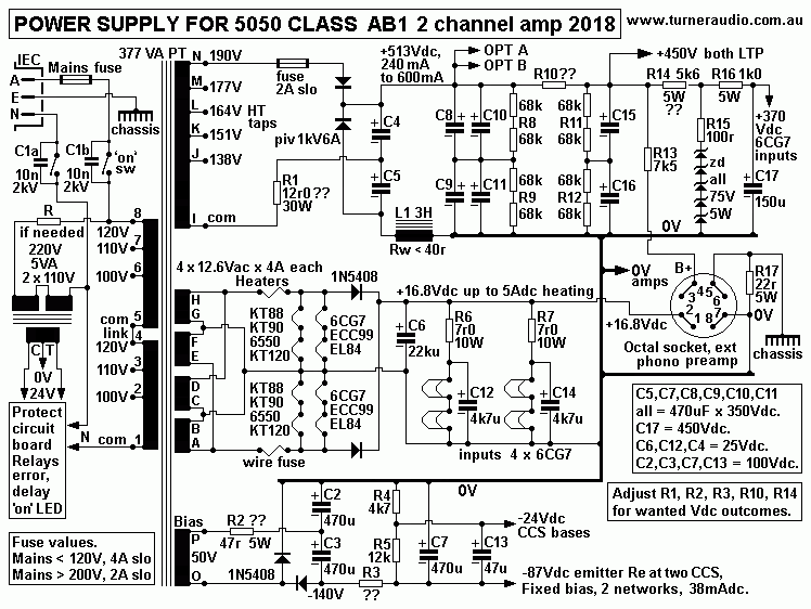
Fig1 PSU schematic for Integrated 5050 amp or other suitable amplifiers.
Table 1. Fill factors for 4 common window sizes.
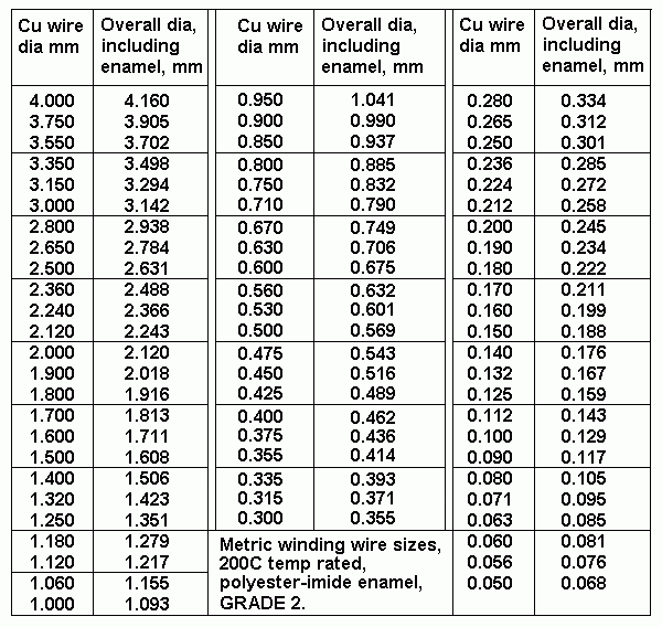
Table 2. Wire sizes, Grade 2 wire, rated 200C max, polyester-imide enamel.
Table 3. Core heat losses.
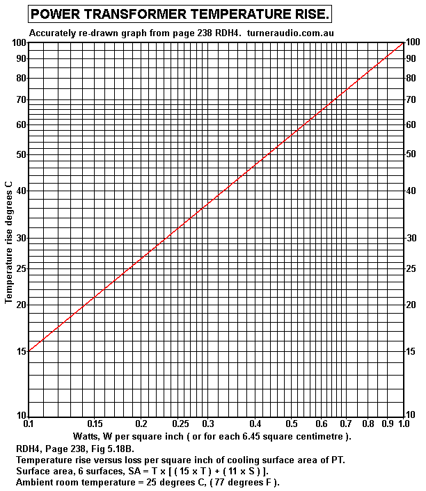
Graph 1. Power transformer temperature rise, degrees C for Watts heat loss per sq.inch.
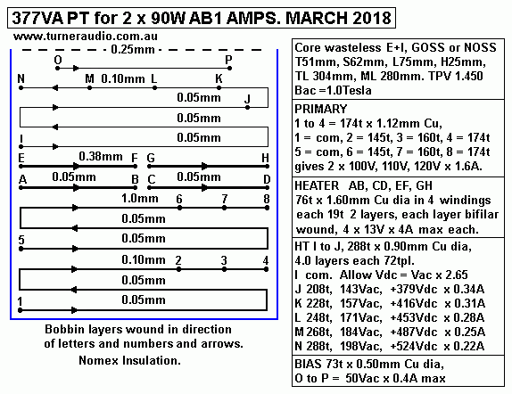
Fig 2. 377VA PT for 2 x 90W channels.
Fig 3. PT for 362VA with GOSS E+I core.
Tables 4, 5, 6 for various Ea and Iadc conditions
-------------------------------------------------------------------------------------------------------------------------

POWER TRANSFORMER design including a lot of calculations.

Schematic of amp power supply must be well understood to design 377VA power transformer.
Fig 1. 5050 PSU for 2 x 50W to 90W class AB UL channels.
schema-5050-psu-2ch-kt120-2018.gif
Fig 1 Schematic includes PT with generous VA rating for 377VA input to make output 343W at idle,
and much more output during high Po class AB of up to 90W / channel.
The PSU suits 4 x KT120, KT90, KT88, 6550, and 4 x EL84 or ECC99 or 6CG7 or 12BH7 for two
LTP drive stages, with 2 x 6CG7 for preamp and input stages.
The PSU can supply all power needed for a good phono amp such as
preamp-rocket-phono-2005.html

Calculations are based on steady idle condition for filaments, input and driver tubes and bias,
but with higher Iac current from HT winding to allow for increase of Idc during class AB operation.
PT should not have T rise above +20C above ambient with NOSS core, or more than +15C with
GOSS core.
PT should remain silent and vibration free during all operation.

The production of B+ must NOT use tube rectifier diodes.

POWER for all tubes :-

AC and DC Filament Heater Supplies.
NOTE. Allow for 4 x KT120 needing 2.1A each. Thus 4 x 6550, KT88, KT90, EL34, KT66 all OK,
4 x KT120 :- 4 x 6.3V x 2.1A = 53W.
4 x EL84 driver :- 4 x 6.3Vac x 0.8A = 21W,
2 x 6CG7 input :- 2 x 6.3Vac x 0.6A = 8W,
2 x 6CG7 preamp :- Idc heaters, include external preamp, 17Vdc x 5A = 85W.
Sub total all heaters = 167W :- 25.2Vac x 6.63A.

B+ ANODE VDC SUPPLY FOR ALL TUBES.
1. For 4 x KT120, Idle B+ power = +510Vdc x 50mA x 4 = 102W.
( At 2 x 90W AB audio Po, max B+ power = 300W, but is not continuous ).

2. Idc in R5+6, R9+10, each 68k, Idc = 520V / 136k = 3.8mAdc, dc power = 510V x 0.0038A = 2W.

3. 4 x EL84 driver stage, Idc is constant = 4 x 14mAdc, dc power = 510V x 4 x 0.014Adc = 29W.
This includes power in R to reduce B+ for LTP to +450Vdc. 

4. 4 x 6CG7 input and preamp tubes, average 5 mAdc each, dc power = 520V x 0.02A = 11W.

5. 5 x 75V Zener diodes, max Idc = 14mAdc, dc power = 510V x 0.014A = 8W.

6. External phono amp, Idc for 3 triodes per channel, each 5mAdc, dc power = 510V x 0.03A = 16W.

7. B- cathode -Vdc bias supply, for 2 x 28mA CCS for 4 x EL84, and fixed bias R networks,
135Vdc x 038Adc = 5.4W.

Sub total 1 to 6 for B+ supplies = 168W.

Total of powers to Primary, and from Secondary windings :-
Primary 377W, 240V x 1.57A
Heaters 167W, 25.2V x 6.63A
HT, doubler diodes, 168W, 190V x 0.88A.
Bias 6W, 50V x 0.12A.
Total of all Sec power at idle = 343W.
( all Fe and Cu loss = 10% estimated for all Sec power = 34W, so Pri VA = 343+34 = 377VA )

For mains input = 240Vrms, Iac = 377VA / 240V = 1.57Amps.

CALCULATE CORE SIZE NEEDED.
Before the metric system made many things easier,
Afe in sq.in = sq.rt VA / 4.44, where 4.44 is a constant.

To find Afe in sq.mm, multiply both sides of equation x 645, because 1.0 sq.in = 645 sq.mm.
Then you get theoretical Afe = 145 x sq.rt VA.

For 377VA, Afe = 145 x sq.rt 377VA = 2,815sq.mm. Here is list of conditions for the ancient
formula to be valid :-
Core = wasteless NOSS E+I, Afe is square centre leg passing through winding with T = S,
145 is a constant for all size units in mm, and VA is input to primary = output from all secs + 10%,
Bac = 0.9Tesla, Frequency = 50Hz, fill factor, ff = 0.3, ie, total of Cu section area of all copper in
window = 0.3 x L x H, stacking factor Sf = 0.95, and current density = 2A/sq.mm.
The "simple equation" is dealing with about 7 different things.
These issues have been well known since 1920s and Sf 0.95 has not changed much at all.
Fill factor ff has improved because winding layers extend closer to Fe because of plastic moulded
bobbins and improved polyester-imide winding enamels, and better insulation than impregnated
woven cotton ( cambric ) made in India, or kraft paper or cardboard, lignum based, still made in
many places.

The Fill Factor.
Consider a typical window size 76.2mm x 25.4mm, The area available for wire = 72mm x 20mm,
and if you have the bobbin full of layer wound turns of 1.0mm Cu dia / 1.093mm oa dia, with no
layers of insulation, the copper area =
0.786sq.mm x [ 72mm x 20mm / ( 1.093mm x 1.093mm ) = 947sq.mm.
Fill Factor = ACu for all turns / window area = 947 / 1,935sq.mm = 0.489.
But insulation layers the typical ff can now be 0.34, with average plastic moulded bobbins,
Grade 2 enamelled Cu wire, and Nomex 401 insulation.

The Bac can also be up to 1.0 for GOSS core because slight improvements have been made
since 1950 to non GO steels.

NOW FOR SOME DIFFICULT BUT SIMPLE MATHEMATICS for CORE T or S.

The PT designer must have a clear list of the normal Vac x Iac and output Watts wanted from
each secondary winding with some allowance for increased power output during use.
To this total he may add 10% for all winding losses and core losses and the total is the
Primary VA rating for the PT.
Using my design ideas, the PT will suit the idle condition and easily cope with +50% total
secondary power for class AB if a sine wave is used up to clipping on both channels.

For the PSU above, total sec power = 343W, allow 10% loss = 34W, thus input VA = 377VA

The designer will know what E+I lams he can source, or has in stock. If he knows Tmm, Lmm, Hmm,
he can easily calculate stack Smm for the wanted VA if he also knows Bac in Tesla, Frequency in Hz,
current density in A/sq.mm.

Assume the copper section area for all turns in the window area will vary with the thickness
of enamel insulation, and for 1.0mm Cu dia wire the Acu = 0.786sq.mm. The oa dia = 1.093mm.
Cu section area for 1 turn = 0.786sq.mm, and the square area needed to contain 1 turn
= 1.093 squared = 1.195sq.mm.
The factor for Acu contained in a given area of winding = 0.786 / 1.195 = 0.658.
For a window with area = 25.4mm x 76.2mm = 1,920sq.mm, the area available for wire allowing for
layered insulations = 15.82mm high x 72.2mm wide = 1,142sq.mm.
This area can contain 1.0mm Cu dia wire turns = 1.142sq.mm / 1.195sq.mm = 956turns and copper
section area total = 956t x 0.786sq.mm = 751sq.mm.

The maximum fill factor = total copper section area / window area = 751sqmm / 1,920sq.mm = 0.391.

But in practice, the factor is difficult to achieve because not all layers will be filled and wire sizes
and ratio of insulation thickness to wire dia varies and in practice the fill factor, ff = 0.34.

The moulded bobbins used for nearly all PT and OPT and Chokes used for hi-fi audio gear have
window size from L76.2mm x H25.4mm, to L38.1mm x T12.7mm and average bobbin wall thickness
plus clearance from Fe = 2.0mm.

Table 1.
Power Transformer Fill factors for 4 common window sizes.
L
mm
H
mm
Window area
Max
bobbin

content height
0.8 x H 
Insulation
layers =
0.1 x H
+ bobbin
base 2mm
All wire ht
including
enamel insulation
Bobbin wind
width =
L - ( 2 x 2mm)
Area
occupied
by
all wire
Copper
section
Area Cu
per LxH

76.2
25.4

1,935
sq.mm
20.32mm 2.5mm + 2.0mm
15.82mm
72.2mm
1,142sq.mm
0.388
66.6
22.2

1,478
sq.mm
17.76mm 2.2mm + 2.0mm
13.56mm
62.6mm
849sq.mm
0.378
57.1
19.05 1,088
sq.mm
15.24mm 1.9mm + 2.0mm
11.4mm
53.1mm
605sq.mm
0.366
47.6
15.8 756
sq.mm
12.64mm 1.6mm +
2.0mm
9.1mm
43.6mm
396sq.mm
0.345
From the table, Fill Factor FF varies from 0.345 to 0.388. It is practical to consider a FF = 0.34
for all window sizes.
Notice that the height of all wire is about 0.61 x window H. 

The current density for Pri and all Secs should be same, but Primary input VA is 10% higher
than total Sec output Watts.

With 377VA at primary input, 343W from all secondaries, total  in + out power = 377+343 = 720W,
and copper section area for all Pri turns = [ Input VA / total Sec W ] x 0.34 x window area
= [ 377VA / 720W ] x 0.34 x L x H = 0.524 x 0.34 x L x H.

For all PT, Primary Cu area all P turns = 0.178 x L x H............................................(1)

Now Np = Vac x 226,000 / ( T x S x Bac x F ). (( Bac in Tesla, F in Hz, and 226,000 is a constant ))

Cu area for 1 Primary turn = Acu for all P turns / Np = 0.178 x L x H / Np
= 0.178 x L x H / ( Vac x 226,000 / S x T x B x F )
= 0.178 x T x S x L x H x B x F / ( Vac x 226,000 )
= 0.787 x T x S x L x H / ( Vac x 1,000,000 )

The area of 1 primary turn x wanted Iac density Id = Primary input Iac.
Primary VA = Vac input x Id x Acu for 1 turn.

Therefore VA = ( Vac x Id x 0.787 x T x S x L x H x B x F / ( Vac x 1,000,000 )
The Vac is cancelled,

Therefore VA = 0.78 x T x S x L x H x B x F x Id / 1,000,000.................................(2)
For any chosen value if T, S L or H, ff = 0.34, dimensions in mm.

Now for wasteless core and where S = T,
VA = 0.78 x 1.5 x T x 0.5 x T x T squared x B x F x Id / 1,000,000,
VA = 0.585 x T to 4th x B x F x Id / 1,000,000,
T to 4th = VA / ( 0.585 x B x F x Id / 1,000,000 )
= 1,000,000 x VA / ( 0.585 x B x F x Id )
Afe = T squared = sq.rt [ 1,000,000 x VA / ( 0.585 x B x F x Id ) ]
Afe = 1,000 x sq.rt VA / ( 0.765 x sq.rt ( B x F x Id )

Afe = 1,300 x sq.rt ( VA / B x F x Id ) for where T = S for wasteless core..............(3)

If B = 1.0Tesla, F = 50Hz, Id = 2A/sq.mm, ff = 0.34,
Then Afe = 130 x sq.rt VA for wasteless core.
This suits those clever ppl who can work out the optimum wire sizes and winding positions
without much reliance on any formula.

The old "safe" formula was  Afe = 145 x sq.rt VA, with fill factor 0.3 and 0.9Tesla.
The better NOSS grade allows 1.0 Tesla and fill factor 0.34, so that Afe can be slightly smaller.

From (2),
S = VA x 1,000,000 / ( 0.78 x T x L x H x B x F x Id )............................................(4)
From this, it is possible to use any chosen T and S and get VA for wanted B and F and Id.

From (2),
T = VA x 1,000,000 / ( 0.78 x S x L x H x B x F x Id )............................................(5)

Examples :-377VA transformer, B = 1.0 Tesla, F = 50Hz, Id = 2A/sq.mm, T = 51mm, wasteless.
With wasteless, L = 1.5 x T and H = 0.5 x T.
(4) S = 377 x 1,000,000 / ( 0.78 x 51mm x 76mm x 25mm x 1.0 Tesla x 50Hz x 2A ) = 49.87mm

49.87mm is less than T51mm, so we would use S51mm which suits a standard bobbin with
T51mm x S51mm.

What is VA rating with T51mm x S51mm, 50Hz, 1.0Tesla, 2A/sq.mm?
(4) VA = 0.78 x 76 x 25 x 51 x 51 x 1.0 x 50 x 2.0 / 1,000,000 = 385VA.
Afe = 51 squared = 2,601sqmm, Np for 240V = 417t. 

What is VA rating with T51mm, S62mm, 50Hz, 1.0Tesla, 2A/sq.mm?
(2) VA = 0.78 x 76 x 25 x 51 x 62 x 1.0 x 50 x 2.0 / 1,000,000 = 468VA
Afe = 51 x 62 = 3,162 sq.mm, Np = 343t.

What is S for chosen T = 44mm, VA = 377, 1.0Tesla, 50Hz, 2A/sq.mm?
(2) S = 377 x 1,000,000 / ( 0.78 x 44 x 66 x 22 x 1.0 x 50 x 2.0 ) = 75.6mm.
T44mm x S75mm is a standard bobbin which could be used.
Afe = 3,300sq.mm, Np = 328t.

What is S for chosen T = 38mm, VA = 377, 1.0Tesla, 50Hz, 2A/sq.mm?
(2) S = 377 x 1,000,000 / ( 0.78 x 38 x 57 x 19 x 1.0 x 50 x 2.0 ) = 117mm. 
There may not be any standard plastic bobbin with S over 117, so make one.
Afe = 4,446sq.mm, Np = 244t

FOR NOSS, Bac = 1.0T and Id = 2.0A/sq.mm for F = 50Hz. Use of 60Hz is possible because
Bac reduces to 0.833T with less core heating. 

FOR GOSS / CRGO, Bac may be 1.1Tesla, Id = 2.2A/sq.mm, F = 50Hz.

Example,
What is S for chosen T = 51mm, 1.1Tesla, 50Hz, 2.2A/sq.mm?
(4) S = 377 x 1,000,000 / ( 0.78 x 76 x 25 x 51 x 1.1 x 50 x 2.2 ) = 41mm
I am not aware of any usable bobbins for T51mm x S41mm. But if bobbin is made with S41mm,
Afe = 2,244sq.mm, Np = 440t.
The maximum dimension is large, shape is somewhat odd, so most ppl would prefer T44 :- 

(4) S = 377 x 1,000,000 / ( 0.78 x 44 x 66 x 22 x 1.1 x 50 x 2.2 ) = 62mm.
Afe = 2,728sq.mm, Np = 362t.  

If T = 38mm, for GOSS, S will be 97mm, and a 38mm x 102mm bobbin is available.
Afe = 3,876sq.mm, Np = 254t.

Note. For the 377VA PT, for max class AB, B+ power may increase +200W for B+ sec to make total sec
power increases from 343W to 543W, and winding losses increase but core loss is constant, so
loss is about 54W so input = 597VA. Primary Iac density slightly increases and HT winding Id may
increase to over 3A.sq.mm, but the condition is temporary, and well tolerated. If PT is in a guitar amp
used by a heavy metal enthusiast who likes all controls on guitar and on guitar amp amp turned up full,
the output tubes become grossly over driven and grid current charges up coupling caps so -Vdc bias
increases and output tubes work in class C, and class C is quite efficient so working PT VA does not
increase exponentially.

CHOOSE CORE SIZE for 377VA PT.

For a NOSS wasteless E+I core, there are a couple of core size choices.
What is VA with T51mm x S51mm for B 1.0Tesla, F 50Hz, 2A/sq.mm ?
VA = 0.78 x L x H x S x T x B x F x Id / 1,000,000.................................(2)
For T51mm x S51mm, VA = 0.78 x 51 x 51 x 76 x 25 x 1.0 x 50 x 2.0 / 1,000,000 = 385VA.

But I prefer the alternative core with T51mm and higher stack of 62mm, and VA = 468, which
will run cooler with NOSS and with working VA = 377.

CALCULATE PRIMARY TURNS AND TURNS PER VOLT.

Core has T51mm x S62mm, for 468VA rating, but for working 377VA at idle. 
Afe = 51mm x 62mm = 3,162sq.mm.

Primary, theoretical Np =
Vac x 226,000 / ( Afe x B x F ) = 240V x 226,000 / ( 3,162sq.mm x 1.0Tesla x 50Hz ) = 343t.

Wire ACu = VA rating / ( mains Vac x Id ) = 468 / ( 240V x 2A/sq.mm )
0.975 sq.mm.
theoretical Cu wire dia = sq.rt ( 28 x Acu / 22 ) = sq.rt ( 28 x .975 / 22 ) = 1.114mm.
From wire size table, try Cu dia 1.12mm, for 1.217mm oa dia including enamel.

Calculate primary turns per layer = bobbin winding width / oa dia.
Bobbin may have cheeks each 1.8mm thick, plus clearance off Fe core so
Bww = 76mm - 4mm = 72mm.
Pri tpl = 72mm / 1.217mm = 59.16turns. Allow for easy fitting of turns, try = 58tpl.

No of Primary layers = th Np / th tpl = 342t / 58tpl = 5.89 layers.
Increase layers to next whole number = 6.0 layers.
Height of Pri wire = 6 x 1.217mm = 7.302mm.

Most PTs have following allowed maximum heights for contents :-
Height of primary winding wire including enamel coating......0.32 x H,
Height of all secondary winding wire incl enamel coating.....0.30 x H,
Height of all layer insulations................................................0.11 x H,
Height of bobbin base plus clearance for bulge...................0.27 x H,

For H = 25.4mm, Pri wire = 0.32 x 25.4mm = 8.128mm.
The chosen Pri wire will fit under allowed Primary wire height.

Note. For all PTs you might wind, the bobbin has a certain base thickness, there are various
thicknesses of insulation and there must be clearance between wound turns and the iron when
E+I are inserted to a wound bobbin. Wires do not lay flat, and after many layers the winding
has bulged and height of bobbin contents plus bobbin base thickness may be found to be close
to the window height H. In general, calculated bobbin contents should not exceed height = 0.8 x H.

Note The VA input to Primary is always between 5% and 15% more than total power from Secs,
so the area occupied by primary turns should be more than all secondary turns to keep the
current density constant.

Height of all secs = 0.3 x 25.4mm = 7.62mm, and heights of Secondary Heater, HT, Bias may
be divided in proportion to the power from each winding.
Total Secondary power = 343W.

For 167W 25.2V heaters, height of wires = ( 167W / 343W ) x 7.62mm = 3.71mm.
For 168W 190V HT, height of wires = ( 168W / 343W ) x 7.62mm = 3.73mm.

The 8W 50V Bias theoretical winding height = ( 8W / 343W ) x 7.62mm  = 0.177mm, which is
a Silly Result, because the bias winding should be rated for the wire size used which will be larger
than needed and say 0.569mm oa dia for 0.4A, or 20W, so Bias winding wire height is theoretically
0.44mm, but it is really 0.569mm, and 1 layer will not occupy the bobbin winding width.
Bias winding may fitted where HT winding does not fill a complete layer. 

Adjusted Np = 6.0 x 58tpl = 348 turns. Np must be an even number to get 2 equal primary
windings to match international mains Vac between 240V in Australia to 110Vac in USA, 100V
in Japan, and 230V in UK.
There will be two windings each 3 layers, and each winding has taps for 120V, 110V, 100V.
Height of primary wires = 6 x 1.217mm = 7.302mm = OK

Calculate turns per volt = 348t / 240V = 1.450.

PRIMARY HEAT LOSS.
 
Check Iac density = VA / ( mains Vrms x Cu wire section area )
1.12mm dia Cu has ACu = 0.986sq.mm. At 2A/sq.mm, Ia = 1.972A and with 240Vac, OK for 473VA input.

For working 377VA,  Primary Iac = 377 / 240V = 1.57A. Primary load input = Vac / Iac = 240V / 1.57A = 153r.

Average Turn Length TL = ( H x 22 / 7 ) + 2 x ( T + S ) = ( 25 x 22 / 7 ) + 2 x ( 62 + 51 ) = 304mm.
RwP = Np x TL / ( 44,000 x Cu dia squared ) where 44,000 is a constant.
RwP = 348t x 304mm / ( 44,000 x 1.12 squared ) = 1.92r.
Primary loss for 377W = 100% x 1.92r / ( 153r + 1.92r ) = 1.22%.
Wire heat = RwP x Iac squared = 1.92r x 1.57 squared = 4.7W.
In other words, Pri loss = 1.22% of 377W = 4.7W.

NOTE. Australian mains is nominally 240V, but could be up to 250Vac or down to 235Vdc. 

Table 2. Wire sizes, Grade 2 wire, rated 200C max, polyester-imide enamel.
table-wire-sizes.GIF

FILAMENT HEATER WINDINGS.

Heater winding for 25.2V x 6.63A must have ACu = 3.31sq.mm or larger for 2A/sq.mm.

Wire dia for given Acu = sq.rt [ Acu x 28 / 22 ] = sq.rt [ 3.31 x 28 / 22 ] - 2.05mm Cu dia.
Wire table says 2.0mm Cu dia for 2.12mm oa dia is close enough.

For 25.2V the turns needed are Vac x tpv = 25.2V x 1.450 =  36.54. But to get 25.2V with load
connected, 38t should be used.
38t x 2.12 oa dia = 80.56mm which cannot fit on one layer 72mm wide.
Therefore use two layers of wire, but each one can use wire Acu > 0.5 x 3.31sq.mm,
say 1.66 sq.mm minimum.

Cu dia for 1.66sq.mm = 1.45mm. Wire table shows 1.50mm Cu dia at 1.608mm oa dia and
38t easily fits on across 72mm width with a spare 10mm of width. The empty 10mm should be
filled with 1.61mm of insulation to keep the following windings flat for full width.

Height of 2 wire layers = 2 x 1.608mm = 3.216mm which is less than allowable height above
= 3.65mm. 1.5mm Cu dia has ACu = 1.77sq.mm and Iac can be 1.77 x 2A/sq.mm = 3.4A.
TWO windings give 6.8A = OK.
RwH for both heater windings in parallel = 38 x 304 / ( 44,000 x 1.5 squared x 2 ) = 0.058r.
Power heat in RwH with max idle current = 6.63A x 6.63A x 0.058r = 2.55W.
Heater RL = 25.2V / 6.63A = 3.8r, RwH loss = 1.5% = OK.

The process of finding the best heater winding arrangement does NOT always follow formulas,
but requires human intuition which has yet to be achieved by application of any AI design program app.
Most computers are so dumb they cannot even read any schematic, let alone any winding diagram.  

HT WINDING.
HT winding for 168W, 190Vac for 0.884A. Turns = Vac x tpv = 190V x 1.450 = 276t.
HT is for doubler rectifier to make +513Vdc at 327mAdc
Acu = 0.884A / 2A / sq.mm = 0.442 sq.mm, Cu dia = 0.75mm.
From wire table, oa dia = 0.832mm. Tpl = 85t.
HT wire layers = 276t / 85tpl = 3.24, so height of all wire = 4 x 0.832mm = 3.328mm, less than
allowable 3.67mm.
3 layers each 85t = 255t, with 4th layer = 21t.
RwHT = 276t x 304mm / ( 44,000 x 0.75 x 0.75 ) = 3.39r
Load on HT winding = 190V / 0.884A = 215r. Loss % = 1.55%
Heat loss = 2.65W.

B- bias winding will fit on 4th HT winding layer and can occupy 50mm of bobbin width.
Bias winding = 50Vac = 73t. Use 73t x 0.5mm Cu dia, 0.569mm oa dia.
Current at 2A/sq.mm = 390mA, much higher than needed.
Negligible heat loss for this winding.

Sub-total of bobbin content height, wire + insulation so far :-
Primary = 6 x 1.217mm..........................................................7.302mm
0.05mm insulation between P layers = 4 x 0.05mm...............0.25mm
0.10mm insulation between P layers = 1 x 0.05mm...............0.10mm
1.0mm insulation between mains Pri to Htr 1.........................1.0mm
Heater 1 winding....................................................................1.608mm.
0.05mm insulation between Htr 1 to Htr 2..............................0.05mm
Heater 2 winding....................................................................1.608mm.
0.25mm insulation between Htr 2 to HT winding....................0.38mm
Sub total to here...................................................................12.298mm

HT winding 4 x 0.832mm......................................................3.328mm
0.20 mm insulation between 3rd on HT layer to B-
B- bias winding 1 x 0.569mm = no height increase.
0.05mm insulation between HT layers = 3 x 0.05mm.............0.15mm
0.25mm cover insulation over all contents..............................0.25mm
Provisional Total sub-total 1..................................................16.026mm

Insulation height = 2.18mm, could be 0.614mm more to reach allowed 2.794mm.
Wire height = 13.844mm, and could be 1.904mm more to reach allowed 15.748mm. 
Clearance off Fe + bobbin base thickness should exceed 0.27 x 25.4mm = 6.858mm.

What are improvements?
The HT winding generates theoretical heat = 2.65W. But with high C values, the charging current
to C for perhaps only 1/5 of each 50Hz half wave and average charge current is 5 times the Idc
current and heat in Rw = average charge Iac squared x Rw / 5, which gives more heat than if the
load is a pure resistance.
If possible, RwHT should be 1/2 the value calculated above. And during class AB operation at high
Po levels, Idc and charge peak currents to C increase, and so does the winding heat.
Wire height so far for Pri and heaters = 7.302mm + 3.216mm = 10.518mm.
Thus available height for HT = 15.74mm - 10.518mm = 5.22mm.

Try increasing HT winding wire dia to 0.90mm Cu dia = 0.99mm oa dia. 
Tpl = 72mm / 0.99mm = 72t. No layers = 272t / 72 = 3.77 layers.
The wire occupies height = 4 x 0.99mm = 3.96mm which should be OK.
Use 4 full layers of 0.9mm Cu dia wire for total HT turns = 4 x 72 = 288t, giving 198Vac,
but it will sag under load a bit.
RwHT = 288t x 304mm / ( 44,000 x 0.90mm x 0.90mm ) = 2.46r.
Allow HT heat loss at average Iac at say 1.3A = 1.3 squared x 2.46 = 4.2W.  

Revise heights.
Sub total to after 0.38mm insulation after Heater 2 winding......12.298mm.

HT winding 4 x 0.99mm............................................................3.96mm
3 x 0.05mm insulation between HT layers................................0.15mm
0.25mm insulation between HT winding and bias winding.......0.25mm
Bias winding = 73t x 0.569mm, part of 1 layer..........................0.569mm
0.25 cover insulation over bias winding....................................0.25mm
Provisional sub total 2.............................................................17.477mm

Clearance off Fe plus 2.0mm bobbin base = 25.4mm - 17.477mm = 7.923mm, exceeds 6.858mm = OK.

TRANSFORMER HEAT LOST IN WATTS.

For CRGO cores, see http://www.aksteel.com/sites/default/files/2018-01/litecarlite201304_0.pdf
For NOSS cores, see http://www.aksteel.com/sites/default/files/2018-01/dimaxm-132013pdf_1.pdf
Use of M4, M5, M6 should be OK for any PT, OPT or choke and give 1/2 the core loss of
M13 NOSS material. For the example PT here, these are the losses :-
Table 3. Core heat losses :-
CRGO, GOSS M4, M5, M6 1.7T
1.5T
1.2T
1.1T
1.0T
0.9T
0.8T
Heat Loss per Kg
2.2W
1.0W
0.6W
0.51W
0.42W
0.37W
0.27W


NOSS M13
1.7T
1.5T
1.2T
1.1T
1.0T
0.9T
0.8T
Heat Loss per Kg
3.3W
2.7W
1.4W
1.2W
1.0W
0.8W
0.7W

The weight of the core must be calculated to find heat loss of the core.
Volume of a wasteless E+I core = 6 x T squared x S. To make things simpler, use centimetres,
cm for T and S.
Density of NOSS or GOSS = 7.6grams / cc.
For 377VA PT, T = 5.1cm and S = 6.2cm, Volume = 6 x 5.1 x 5.1 x 6.2 = 968cc, weight = 7.35Kg.
Core heat at 1.0T for NOSS = 7.35Kg x 1.0W/Kg = 7.35W. 

The same cores with GOSS / CRGO at 1.0T have 0.42W/Kg for heat = 3.1W which is a minor factor
in core heating.

In theory, use of higher Bac at say 1.2T with GOSS gives 0.6W/Kg = 4.4W heat, but Np can be reduced
by factor = 0.625, so a larger wire sizes can be used with much lower Rw so higher VA rating.
But the PT may be noisy, and vibrate a bit. 

In hi-fi amps I always found Bac higher than 1.0T leads to vibration and noise.
Even with toroidal or C-cores which usually are GOSS, the noise and vibration are a problem and it is
always necessary to pot the transformer with 2 pack potting mix, or casting resin with sand.
The problem with potted PTs is that its like wrapping the PT in a blanket, and heat cannot get
out of the transformer so easily. The result is that copper and iron runs hotter and the outside of pot
can run slightly hotter.

Where you do find usable NOSS, it may not like running at 1.7Tesla.
AK steel seems to say its possible without complete core saturation. I found about 1.3T was max
for old Lycore 150 NOSS. I suspect 150 meant 1.5W / Kg but Bac was never specified.  

The total winding heat for 377VA PT :-
240V Primary = 4.7W.
Filament heater = 2.65W,
HT = 4.41W.
Bias = negligible
Total Cu heat = 11.76W = 3.11% of 377VA, < 5%, = OK.

Total loss for Fe and Cu = 7.35W + 11.76W = 19.11W = 5.07% of operating 377VA.

ESTIMATING TEMPERATURE RISE.

On page 238, RDH4, there is Fig 5.18B giving Temp rise versus W / square inch of
external core area.
Graph 1. Power transformer temperature rise, degrees C for Watts heat loss per sq.inch.
PT-temp-rise-vs-W-per-sq-in-RDH4.GIF
On page 237, RDH4 formula to calculate surface area of power transformer with wasteless E+I :-
Surface Area = T x [ ( 7.71 x T ) + ( 11 x S ) ].

Unfortunately, this formula for wasteless E+I seems incorrect.
The dimensions of a wasteless core PT with lams laying flat on chassis are :-
Plan area, top and underside = 2 x ( 2.5 x T ) x ( 3.0 x T ) = 15 x T squared.
The 4 vertical sides area = S x ( 2.5T + 3T + 2.5T + 3T )  = S x 11 x T.
The surface area omits the slight increase due to bell end covers or projecting windings.
The RDH4 formula forgot to include for heat radiation from underside of PT.

The Corrected Formula is SA = T x [ ( 15 x T ) + ( 11 x S ) ].
The core radiates most heat, and convection with air flow gives some cooling.

The formula should assume the PT hangs in air of a room, is not potted, and without bell-end
covers, and is unaffected by how it is fixed to a chassis or by what tubes are located nearby,
or the temperature of the under-chassis volume. Usually, the PT runs hotter when on a chassis
of amp than in free air because of hot tubes nearby.
I don't know exactly how RCA staff composed the graph, but there is no such graph on Internet
because the latest generation is Bone Lazy.

For 377VA PT with T 5.1 cm and S = 6.2 cm, SA = 5.1 x [ ( 15 x 5.1 ) + ( 11 x 6.2 ) ] = 738sq.cm
= 114 sq.in. For total Fe + Cu heat = 19.11W, heat / sq.in = 19.11W / 114sq.in = 5 / 105 = 0.167.
From Graph 1 the T rise = +23C. If ambient T = 25C, PT temp = 48C.

What if core was smaller size with T51mm and S51mm, and GOSS was used,
but with same wire, Bac, and Id ?
Weight = 6.05Kg, and core loss = 0.42W/Kg x 6.05 = 2.54W.
Copper loss is less because turn length is 22mm shorter = 282mm.
Copper loss = 11.35W x 282mm / 304mm = 10.5W.
Total Fe + Cu loss = 10.5 + 2.54 = 13W.
With surface area is less = 676sq.cm = 105sq.in and W/sq.in = 10.5W / 105sq.in = 0.1W / sq.in.
T rise = +15C, and if ambient = 25C, PT = 40C, which feels much cooler than 48C, and you
will find the results are pleasing.

I have wound a number of PTs with old NOSS made after 1960, and sometimes used Bac = 0.8T
where core loss may be assumed to be = 0.7W/Kg.
One example is the PT in amp at 2323-triode-integrated-6cm5.html
This OPT has T38mm x S62mm and core weight = 4.1Kg, and surface area = 475sq.cm = 74sq.in.
VA at idle = 154W.

The VA rating for core is 160VA according to above formulas Core volume = 537cc, weight = 4.1Kg.
Fe Core loss = 4.1Kg x 0.7W/Kg = 2.9W.
Cu loss estimated at 5% of load of VA = 7.7W.
Total heat = 10.6W = 0.143W / sq.in, and T rise should be +18C so that T = 43C on a day of 25C.
I can leave my hand on the transformer without pain, and the RDH4 graph appears to work about right.
The measurements I made indicate PT T at about 43C.

It seems only RDH4 has presented the world with a simple graph that relates T rise above ambient to
the number of watts of heat and the surface area of the transformer, for most PTs used in old radios
and old or new amplifiers.

Just what comprises the core loss? it is present with or without secondary loads connected.

The primary current measured for PT primary consists of current flow in the primary inductance,
and harmonic currents due to eddy currents and hysteresis of iron creating a non linear load to primary
input Vac. As the Vac peaks swing above Bac = 0.6Tesla, the current in primary increases non
linearly as the core moves towards saturation. If Vac pushes Bac to saturation and above, the magnetic
field ceases oppose the current flow so the load where Vac exceeds the mains becomes the winding
resistance RwP and current becomes extremely high. If you have a primary meant for 120Vac mains,
and it is used where a 240Vac mains exist, the mains fuse should blow instantly.

I recently tested a large PT for 240Vac input, with wasteless NOSS E+I core, T38mm, S75mm,
L57mm, H19mm. Transformer SA = 530sq.cm = 82sq.in, Volume 650cc, weight 4.94Kg.  

No secondary loads were connected.

I applied a switch-variable 50Hz mains Vac from 14Vrms to 240Vrms.
The mains input Vac which measured 240Vrms had  flat topped waves with about 5% 3H+5H etc,
due to hundreds of other local ppl using electrical appliances with rectified mains inputs. My switched
Vac source is like a variac, and had a 1:1 isolation PT before it so Vac could be reference safely to my
local Earth connection.
I used a 10 : 1 Vac divider to use to view mains Vac on on channel of CRO, and was able to view
primary current in other channel using 1r0 x 10W in series with neutral line to Primary.

There was very little THD in Iac wave up to 50Vac input, indicating the primary was acting like a
pure inductance. The Lp reactance rose from 1k1 to 2k7 at 50Vac because permeability, µ, increased
from say 0.06T at 14Vac to 0.21T at 50Vac.
The high THD of mains input Vac did not appear in Iac waves because 3H at 150Hz is much reduced
by higher L reactance at higher F. There may be other reasons I am not aware of.
But above 50Vac, Iac wave peaks became flattened and by 100V 3H = 20% approx.
At 150Vac, the flats began sloping upward and 3H increased, and there was probable other 5H, etc.
At 180V there are peaks at end of flats, and as a result of phase shift of 3H relative to the 50Hz.
At 240Vac, each 1/2 Iac+ wave goes up to 1/2 max, then levels, then up to a peak at max before steep
drop to the same inverted shape for the Iac -1/2 wave.

The Iac wave was measured with DMM rms meter, and the primary input impedance =
1k1 at 14Vac, 3k0 at 70Vac, 3k5 at 160Vac, then reducing to 2k7 at 240Vac. I have no idea of the
max Bac, but if I assume it is 1.0Tesla, then max Zin is at 160Vac where Bac may be 0.65Tesla.
Primary Lp at 160Vac is probably about 12H, quite a good high figure.
At 240V, Iac = 86mAac, so VA with no load = 20VA, and it is possible core heating = 10W. 
The other 10VA is due to Iac in primary inductance which causes no heating. 
This sample transformer has a VA rating of about 252VA, Primary input load = 228r, RwP = 3r2,
Pri loss = 1.4%.
I left the PT on wood bench for 4 hours with no load, and recorded ambient T and core T,
and T rise = +11C. The RDH4 graph begins with rise of +15C at 0.1W / sq.in. +11C indicates I had
0.07W / sq.inch, so with SA = 82sq.in the core heating power = 0.07 x 82 = 5.74W.
This was a very good result with a NOSS core because many other old PTs I have tested will get too hot
even with no load connected.

ABOUT DIODES.
1N5408 have 3A rating which may mean 3A continuous. Data says forward voltage = 1.0V which is
true for highish currents > 0.5A. So on R = 1.0 / 3A = 0.33r, and diode heat = I squared x R =
 3A x 3A x 0.33r = 3.0W. They will feel  hot if you touch one. If the current = 20A, the forward voltage
is still 1.0V, so R = 1V / 20A = 0.05r and heat = 20A x 20A x 0.05r = 20W, and the 20A could not
last for longer than about 0.14 seconds or else the diode would explode with heat at PN junction going
high enough to melt and vaporize the hard plastic diode capsule.
The data says diode will survive a short pulse of 200A. OK, but only if pulse lasts 15uS, and not more
often than every 10mS. Peak inverse V = 1,000V for 1N5408. It means that if you have a HT winding
with CT at 0V for 320Vac - 0V - 320Vac, the Vdc = +450V. The winding swings +/ 450V peak so
max PIV = 900V. With a bridge rectifier winding of 320Vac, two diodes conduct during charging and two
are in series with 450Vpk across each. Therefore I like to use 2 x 1,000V diodes in series where I replace
tube diodes with Si diodes to make +450Vdc.
In a doubler with 200Vac max at one winding, max piv = 560Vpk so one diode is OK but in some amps
I have used 6A rated diodes with 1000V piv. Where iac is high, I have sometimes used 2 parallel diodes
with 1r2 in series with each diode to force each to have fairly equal peak Iac. P600M are OK

Do not use 1N4007 for a power amp. These have 1A rating for continuous current, and peak short term
current rating of 30A. These diodes soon overheat and are destroyed if you had 3A continuous because
their size is small and you get a high T rise, and if there is a short circuit you want a fuse to blow, not
the diode, and not the transformer winding.

In any B+ supply with Si diodes, peak Iac during charging can be surprisingly high. Diode peak current
is limited by the sum of diode R + HT Rw + primary RwP + mains supply resistance at the wall plate
which includes house wiring to the heavy supply wires in the street.
If the Idc flow = 332mAdc, and mains Vac is a sine wave, and C = 470uF, and there was no series R
the Iac peak charge could be 5A. But I have made SS amps with +/-70Vdc and used 2 x 100,000uF
and 35A rated bridge diodes with 50V-0V-50V winding and at 700W output the dc power = 1,000W
and Idc = 7A at each +/- rail and peak charge may be 35A. It has lasted the test of time.

The mains often has flat topped Vac waves where the flat is about 1/5 of each 1/2 wave, so charge current
remains fairly constant and not too high but when most ppl are asleep, wave is more sinusoidal so peak
charge Iac is higher, and PSU must be built with that in mind.
Using some added R between HT winding and diodes before high C values can much reduce peak
charge currents, but it makes the B+ output resistance higher. But that is going to always be low enough
with a small R series R. The B+ will not be as high with any series R but in case of 377VA PT the HT Vac
is rated at 198Vac to give +525Vdc with some loading, but the series R can drop this to +510Vdc without
lowering max Po much, but it may reduce peak charge Iac by -50% or more, so the HT winding runs cooler,
and it does not matter if R has 10W of heat. 10r0 should halve the peak charge current to each 470uF in
Fig 1 PSU for doubler diodes. 10r0 should be 30W rated at least.

The HT winding should have 5 taps at 20t apart which allow other tubes to be used.

The windings will bulge as turns are wound on and will never lay flat where wire is inside the core,
so the clearance of 4.7mm is needed. It may be possible for bobbin content to be 2mm higher but
the wound bobbin would need to have slow setting epoxy varnish applied while winding and the
wound bobbin then cramped up with wood blocks and a G-cramp while still held on lathe chuck.
It is a hugely messy job with toxic fumes. The wound bobbin is left cramped for 2 days before
removal from the lathe.

The windings must be drawn up carefully for any winding trades-person to easily follow.
If this person is YOU, you need to wind a few chokes first with neat layer winding before winding
a complex PT like this one.
It is extremely easy to become totally confused when winding tube amp PT or OPT because there
are so many connections and taps.

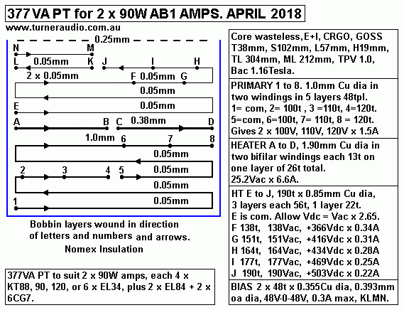
Fig 2.
377VA PT for 2 x 90W channels.
377VA-PT-T51mm-2x90W-AB1-amps-March-2018.gif
Fig 2 shows a good design for 377VA PT to power your favourite amp that could make
2 x 90W or 1 x 180W.
It is heavy. The two OPT will be heavy, and then there is a choke, and the chassis must
be steel and be strong enough so it will not bend if the amp is dropped off a bench, or badly
handled by conveyor belts and careless ppl during transport.

( But a thief will find it difficult to steal, and a few have been caught trying to run away with
the amp, which they usually drop :-)

TRANSFORMER CORE WEIGHT.
For all iron cores :-
Iron core Volume =  [ ( plan area of assembled E+I ) - ( 2 x { L+H } ) ] x stack S
,
dimensions in cm.

Wasteless E+I Volume = [ ( 3T x 2.5T ) - ( 2 x { 1.5T x 0.5T } ) ] x stack S
,
dimensions in cm,
Simplified wasteless Volume = 6 x T squared x S.

Weight = core volume in cc x density of transformer steel density in gm / cc.

Density of NOSS or GOSS = 7.6 grams / cc.

Options for For NOSS wasteless core choices for PT :-
Bac = 1.0Tesla, F = 50Hz, Id = 2A / sq.mm.

1. T = 5.1cm, S = 6.2cm, VA rating = 468. Core volume = 6 x 5.1cm squared x 6.2cm = 967cc.
Weight = 7.35Kg, SA = 114sq.in ( = 738sq.cm. ) For working 377VA, total losses = 20W,
W / sq.in = 0.175.

2. T = 4.4cm, S = 7.5cm, VA rating = 374.
Core volume = 871cc. Weight = 6.62Kg, SA = 101sq.in ( = 653sq.cm. )
For working 377VA, total losses 25W, W / sq.in = 0.247.

3. T = 3.8cm, S = 11.7mm, VA rating = 375.
core volume = 1,013cc. Weight = 7.70Kg, SA = 109sq.in ( = 706sq.cm. )
For working 377VA, total losses 25W, W / sq.in = 0.23.

The T44mm x S75mm core seems like good value with least weight, but also least
surface area so may run hottest of 3 options because W / SA factor is highest.
Use of GOSS core would reduce heat considerably without any other changes.

What if non wasteless E+I was used? It is a silly question because you cannot buy small
quantities of cores with say T = 32mm and windows = L76mm x H25mm. You could buy it
in 1955, and it was more expensive than wasteless because cutting the shape produced
waste, and waste costs money.

But you might use C-cores in double O if you can ever find any for sale with build up say
16mm for T dimension of 32mm, with windows 76mm x 25mm.

The turns can be the same as for wasteless E+I with T51mm x S62mm wasteless = 348t.

But Afe must be same as T51mm x S62mm = 3,162sq.mm.

Therefore C-core S = 3,162sq.mm / 32mm = 99mm, say 100mm, so that perhaps 4 x C-cores
are used, one pair stacked on top of other pair each with strip width 50mm, a standard size.

C-core volume = No C-cores x strip width x build up x average length of wound strip
=
4 x 5.0cm x 1.6cm x [ ( 2 x { 7.6 +2.5 } ) + ( 1.6 x 22/7 ) = 4 x 5.0cm x 1.6cm x 25.2cm = 807cc.
Weight = 6.13Kg.

To determine the temperature of PT.
Surface Area SA for 4 x C-cores for double O, each with build up 16mm for T32mm,
window L76mm x H25mm, and total strip width giving S = 100mm =
( 2 x oa plan area ) + ( distance around external curved shape x total strip width )
= ( 2 x 11.4cm x 10.7cm x 0.95 for curvature ) + ( 41.6cm x 10.0cm  )
= 648sq.cm = 100sq.in. ( The C-core weight and surface area is almost identical to
use of wasteless T4.4cm x S7.55cm. TL is nearly same. Np is same, but C-cores
have bigger window than T44mm E+I, so copper losses should be lower because
wire size is larger. 

C-cores are always GOSS, and will run cooler than NOSS but be 3 times the price
of NOSS E+I. So C-cores do not give any DIYer or small volume manufacturer a free lunch.

So far, for E+I, Cu losses are twice the Fe losses even with NOSS core. With GOSS,
T rise for 377VA PT should be carefully worked out with Bac = 1.1Tesla and Id = 2.2A / sq.mm
and with less turn length and less surface area and lower weight.
But GOSS E+I can cost much more than NOSS.
--------------------------------------------------------------------------------------------------------
Many DIYers may be tempted to use core material taken from old PT made 50+ years ago.
I did this often during my 20 years career being an audio tech and "amp worker" and I found
some awful iron with high loss W / Kg and low permeability was just fine to use in dc filter
chokes where permeability needed was often below 700.
There was a lot of junk NOSS core material that is not as good as anything made by
AK steel and if you use it at 1.0Tesla for a PT, it runs so hot after 4 hours in warm weather
that you might be able to fry eggs on it. Its more than 50C. Hot tubes nearby help it to be
hotter. Buying small amounts of C-cores of GOSS E+I has become difficult. Nobody wants
to sell say 40Kg for your amp project. They like orders for 40 tonne or 4,000 tonne.

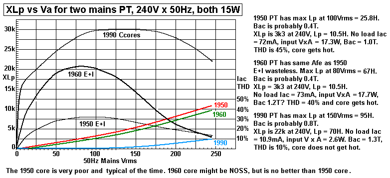
Graph 2. 1950 E+I lams and 1990 C-cores for 15W mains trans.
Graph-VL-vs-XL-EI-Ccores.GIF
This shows the difference between poor 1950 and 1960 E+I core material and 1990 C-cores for
three small PT with same Afe.
The no load VA input for 1950 and 1960 PT is high, and a high % of that VA heats the core
But the 1990 C-cores have far lower no load input VA and make less heat. 

The 1950 and 1960 PT had wasteless E+I E+I cores with T25mm x S30mm, and appeared to
have VA rating of about 20W. With Pri input = 240Vrms, the Pri load
= Pri RL = Vac squared / VA rating = 240V x 240V / 20W = 2,880r.
Both the 1950 and 1960 PTs have XL 3k3 at 240Vm so that
The Pri RL is not much less than the XL so core losses would be considerable. The
magnetizing Iac = 240V / 3,300r = 72mA. VA = 17.3W. I don't know how much of that power
heats the core, and how much is just Iac flow through primary Lp, no heat is generated in Lp,
although some heat in windings is due to Rw x Iac squared.

The 2,880r load Iac = 240V / 83mA Because inductance is reactive, the total Iac input is not just
the sum currents, but maybe 112mA, and total input VA = 27W.

Now the 1990 PT with double C-cores with Afe = T22mm x S25mm and window 51mm x 16mm
has XL at 240V at about 23k, and THD in Iac is only 10% so the magnetizing current is very
much less than for the E+I, so the core cannot heat up much. The window is a much larger
size than 12.7mm x 38.1 for T25mm E+I, so the wire size can be larger and so nearly all the
heat in PT is in the winding and not the core, so the VA rating is probably 30W, and Pri load
could be 1,920r.
Obviously, the C-core tranny is superior to the E+I.
---------------------------------------------------------------------------------------------------------
I should mention toroid cores. Buying toroid cores may be easy, but winding them requires a
toroid winding machine which is difficult to make yourself.
They can be fine for PTs but I found they need to have Bac < 1.0T to get noise and vibration low.
Many commercial toroid core PTs which you can buy were designed for 220Vac or 110Vac so
when used in Oz with 240V the Bac might be 1.3Tesla+ . All the toroidal PT I bought from Jaycar
and Harbuch were far too noisy to use in a hi-fi amp because you can hear them humming
metres away.

Toroidals might be OK for a factory where noise and vibration does not matter.
I found they got hot, and produced high external 100Hz stray magnetic fields so they needed
to be potted. None had varnished windings and all relied on wire tension pulling on polyester
tape used for insulation between Pri and Sec. So the micro-movement of wires is allowed to
occur. On many toroidal PT, wires are messily layered, and so I never used any toroid cored
PT in any amp except one. This had 800VA rated core, and ran at 1.2T, and was noisy.
I increased the primary and secondary turns by 30% to stop the noise by getting Bac < 0.8T.
I added the extra turns using a hand shuttle made with a 20mm wooden dowel about 1 turn
long, with V-cuts each end to hold 30t of wire on shuttle, then unwound onto toroid core by
passing shuttle through the centre hole 30 times for 30t turns, and each turn was pulled tight,
and kept tight for the next turn. It was a painful exercise which took two days.

The best toroid core PT use woven polyester tape for insulation so that when soaked in liquid
varnish it can easily penetrate the fill the voids to expel the air,wetting every surface before
heating to 125C for 4 hours. The the best toroid PTs are potted, and then you have a very
good PT. Core loss in W/Kg is so low for strip wound GOSS that it may be ignored. When
potted, the pressure on windings in pot is low. And you pay through the nose for such PTs
if ever you can find them. Plitron in Canada may have something like this.

I cannot recommend toroid PT or OPT and certainly not for DIYers. Try watching Google
Videos on toroid coil winding, one is https://www.youtube.com/watch?v=v-Upv7Mo7YU

BEWARE the sites claiming to offer toroid transformer calculations. NONE I found were
any good, or were so riddled with mistakes and bad grammar they were useless.

The turns for primary must obey the same equation as for any E+I or C-core, ie,
Np = Vac x 226,000 / ( Afe x F x Bac )
And for any hi-fi amp, the Bac should not exceed 0.9T for 50Hz.
--------------------------------------------------------------------------------------------
SOME GENERAL INFORMATION :-

Amorphous cores.
These are defined at https://en.wikipedia.org/wiki/Amorphous_metal_transformer

I have never tested any amorphous core PT or OPT sample but from what I read it is said
they saturate at Bac less than 1/2 that of GOSS. They are becoming popular in the heavy
power industry where multi kW or MW are involved. The core heat loss is low, so although
the Afe has to be twice that for GOSS, less power is wasted keeping the transformer cool.
For the PT detailed on this page the Afe would have to be doubled to allow the winding
shown to be used. Amorphous cores are very brittle, and dropping a transformer could
ruin it. The cost is prohibitive, and DIYers should ignore these cores.

Nickel-iron alloys are very expensive, and difficult to source and use is not justified for any
power transformer. In OPT, I see little benefit, but in SE OPT there may be less slightly THD
so this enables all sorts of silly claims to be made to boost sales of amps with Ni-Fe alloy
cores or those with a mix of Fe-Si plus Ni laminations. I base my design on wasteless GOSS
E+I laminations or C-cores, or NOSS if you are poverty stricken, and you don't mind wasted
heat and high weight. Where there is a +20C temperature rise above ambient for a generously
designed PT with NOSS, the same sized GOSS core with same winding and load may give
+10C after 4 hours. The T rise for GOSS or NOSS with low Bac will be mainly due to copper
losses being more than core losses.
------------------------------------------------------------------------------------------------
To examine the properties of some unknown quality iron for a given applied mains
voltage at 50Hz, you should wind a test coil on a bobbin suitable for the sample of iron you have.

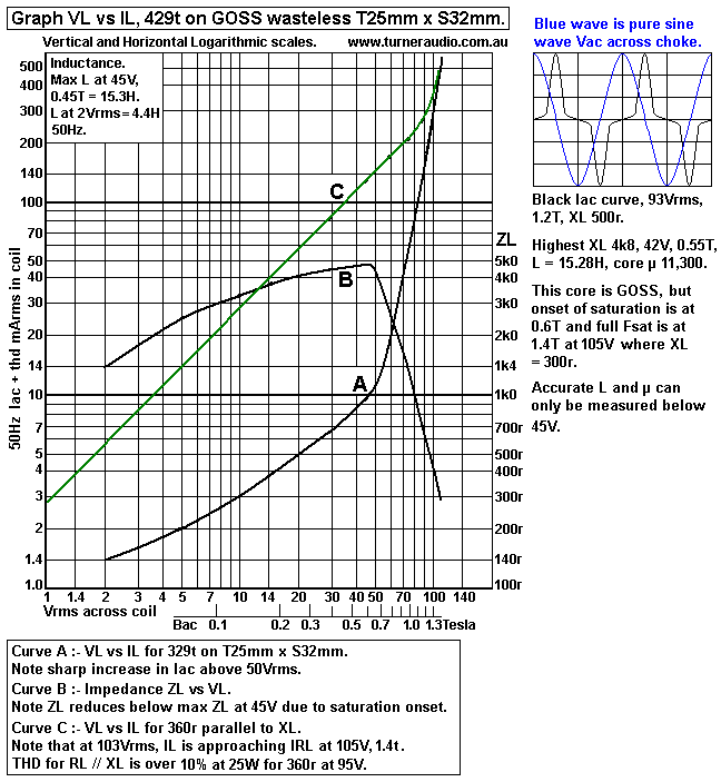
I made a test coil 429t x 0.8mm Cu wire dia to fill the bobbin window to suit T25mm x 32mm stack.
The wire was random wound. The E+I lams filled the bobbin and were fully intermeshed.
I used switched levels 50Hz, 14.5Vrms, 29Vrms, 44Vrms to 87Vrms.
Maximum XL was 4,700r at 44Vrms, and THD = 10%.
L = 4,700r / ( 6.28 x 50Hz ) = 15H.

Graph 3.
Graph of VL vs IL and VL vs XL for 50Hz. 
Graph-VL-vs-IL-429t-50Hz-T25-S32.GIF
The core of T25mm x S32mm could be rated for 25W PT. 
In this case, if Bac is allowed to be 1.0Tesla at 76Vrms x 50Hz, and if this winding was for
a PT primary, then the Pri load = 76V squared / 25W = 230r with N = 429t.
The
XL = 1k2, magnetising Iac = 64mArms, load current = 334mArms.

Now if Vac input = 240Vrms, Bac = 1.0T, N will have to be 1,355t, and load = 2,282r,
and XL may be 10k and magnetizing Iac = 24mA, and load Iac = 105mA. The total
magnetising VA = 5.76, and I don't know what amount of this heats the core.
But for GOSS, the core loss / Kg at 1.0T is about 0.5W per Kg, and this core weighs
0.912Kg, so expect heat = 0.45W, and I doubt the core would get hot.

Now L = 1.26 x Nt squared x Afe x µ / ( ML x 1,000), where L = Henry, 1.26 and 1,000
are constants, N is the No turns in coil in thousands, of turns, Afe = Tmm x Smm,
µ is permeability, ML is magnetic path length in mm.

µ = L x ML x 1,000 / ( 1.26 x Nt squared x Afe ).

For this example, at 50Hz, µ = 15.3H x 138mm x 1,000 / ( 1.26 x 0.429 squared x 25mm x 32mm )
= 11,381.

The core sample must be GOSS, because anything other than GOSS will give less L and 
lower µ < 3,500, and that always means the XL at 1.0T would be much lower and core
heating is higher.   
 
You can also work out magnetic field strength Bac in Tesla because you have know Vac,
Afe, N, F.
 
Bac = Coil Vac x 226,000 / ( Afe sq.mm x N turns x 50Hz ), where Bac = Tesla,
226,000 is a constant.

This case, Bac = 76Vrms x 226,000 / ( 25mm x 32mm x 429 x 50Hz ) = 1.0T

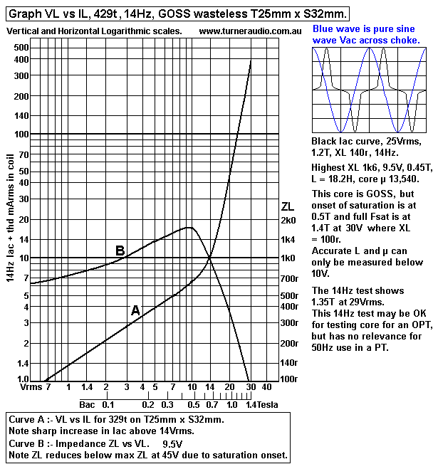
If I wanted to see if the core was suitable for an OPT, I would have to use a 14Hz test
signal and draw the graphs to find where Fsat would occur.

When I used a power amp to apply up to 40Vrms at 14Hz to the coil, I found :-

Graph 4. VL vs IL, and XL, 14Hz.  
Graph-VL-vs-IL-14Hz-GOSS-EI-25x32core.GIF
The graphs here show that the highest XL, and thus highest µ and L are where Bac is
between 0.4Tesla and 0.7Tesla at the top of the arched graph.

The µ of core and XL and the THD that is generated by core is mainly important for OPT.
For PT, which operate at only 50Hz or 60Hz, the noise, the core heating and efficiency
is the biggest concern. There is nothing wrong with using NOSS E+I if you have the
Bac max at below 0.8T. The magnetizing currents are much smaller than trying to
have Bac at 1.2T, for best GOSS. The lower Bac is not efficient, because the
you need more turns per volt and the wire takes up room so the core for a hi-fi amp PT
will be larger than a PT with same VA rating and used in a factory.

Second hand E+I laminations.
These become available when an old E+I transformer has been retired, or it has fused
and those replacing the transformer find it cheaper to buy a new one from China than
re-wind it.
So, providing old laminations are not rusty after being left in a pile in the rain for 20 years,
You may re-use their cores. DO NOT RE-USE THE WIRE.

During my 18 years as "amp worker", aka audio tech, I acquired a pile of old fused
transformers which I dismantled for re-use of the cores. Some were very well varnished
and it was difficult to separate Es from Is.

The best way to prepare old iron for re-use is
1. Remove all bolts, bell ends, and yokes. Leave the wire on.
2. Use an old oil drum with holes in the bottom to allow air flow and stack fire wood
around the pile of transformers.
I have a fireplace in my lounge, and and I built small fires around the gathered cores.
3. Cremate the cores, and give good wishes to the transformer spirits ascending.
4. Don't breathe the smoke, it is a little toxic because a small amount of vaporised
un-burnt varnish and plastic is in the smoke. My neighbours are not close, and they
kept their windows shut tight on freezing July late nights.
5. The transformers only need to appear dull red, there is no need for more than 900C.
6. Let the fire die down. Do not quell the fire with water.
7. Next day rake out the cool transformers and remove loose ash and dust, and
take them to the workshop where you should have a nice solid wood bench and a
large vice.
8. The roasted trannies will appear kind of partly loose, and you may find the E+I
just fall apart and out from the coil of wire. The wire goes to the bin for scrap to pay
for the beer at the Christmas party.
9. Clean up the mess you make and you will find the lams are ready for re-use.
The oxide coating insulates each lam from the next. But where lams are rusty,
discard them.
 10. You should find the magnetic properties are unchanged or even improved by
the slow heat which in effect is annealing.

Testing second hand iron is essential. The magnetic properties of iron from old
transformers does not change over time for GOSS or NOSS.
However MOST old E+I lams you find will be NOSS, and you need to find out the
properties, ie, max µ before re-use. Most µ max is under 3,500,with quite a lot only
2,500, and with low µ the Bac max possible is under 1.2T, so to be sure you don't
end up making a hot running PT, never have Bac higher than 0.8T.

Winding transformers successfully is a skill that must be learnt and practised, like
shearing sheep, laying bricks, sewing clothing, and a winding lathe is needed along
with a great deal of patience and knowledge to avoid the transformer having a short
life, or to find yourself dealing with a tangle of wires and your mind is confused.

Before winding any PT or OPT you should learn to wind a nice layer wound DC
filter choke.

I suggest you read my page at output-trans-winding.html
------------------------------------------------------------------------------------------------------------------
377VA PT for 377VA with 38T wasteless E+I for Fig 1 above.
Core should be T38mm x L57mm x H19mm.

This is usually more easily available than T51mm or T44mm material.
 
Bac = 1.1Tesla, Iac density = 2.2A/sq.mm, 50Hz, 240V mains.

Primary VA = 0.78 x L x H x S x T x B x F x Id / 1,000,000
0.78 and 1,000,000 are constants, T, S, L, H in mm.
Therefore if you choose T38mm with L57mm x H19mm, you can calculate S :-
S = Pri VA 377 x 1,000,000 / ( 0.78 x 38mm x 57mm x 19mm x 1.1T x 50Hz x 2.2A/sq.mm )

= 97mm, so use 100mm because this is a standard bobbin size with 38mm x 100mm core hole.

From this the TL = 340mm, SA = 643sq.cm = 99.7sq.in.
With GOSS, expect efficiency = 95%. Total Fe + Cu heat loss = 5% x 377VA = 19W.

SA = 642sq.mm = 99sq.in, W / SA = 19W / 99sq.ins = 0.191.
T rise from Graph 1 above = 26C.
If room temp = 20C, PT temp after 2 hours = 46C. 

Np = 240V x 226,000 / ( 38mm x 100mm x 1.1Tesla x 50Hz ) = 260t.

For total Pri input = 377W and mains = 240Vac, input = 1.57A.
Core window = L57mm x H19mm = 1,083sq.mm
From Table 1 for T38 x L57mm x H19mm, wire occupies area = 605sq.mm, and total
Area Cu section, all wires, can be 0.34 x 1083sq.mm = 368sq.mm.

Primary uses 0.52 x 368sq.mm = 191sq.mm, and for 260t, Acu per turn = 0.735sq.mm.
The wire size might be 1.0mm Cu dia for Acu = 0.786sq.mm, Id = 1.57A / 0.786sqmm
= 1.99A/sq.mm, less than 2.2A/sq.mm = OK.

1.0mm Cu dia wire has oa dia = 1.093mm
Bobbin wind width = 53mm, tpl = 53 / 1.093 = 48t. No layers = 260 / 48 = 5.41.
Use 5.0 layers of 48tpl = 240t. Divide into two windings for 120V + 120V for international
mains Vac, using 2.5 layers each.

Turns Per Volt = Vac input / Np = 240V / 240t = 1.000tpv.
Corrected Bac = 1.16Tesla = OK.

Allowed height maximums :-
Height of primary winding wire including enamel coating..........0.32 x H = 6.08mm.
Height of all secondary windings including enamel coating......0.30 x H = 5.70mm.
Height of all layer insulations.....................................................0.11 x H = 2.09mm.
Height of bobbin base plus clearance for wire bulge.................0.27 x H = 5.13mm.

Height of Pri wire including enamel = 5 x 1.093mm = 5.46mm, < 6.08mm, probably OK so far.
Average tun length TL = 340mm.
Primary RwP = 240t x 340mm / ( 44,000 x 1.00 squared ) = 1.85r.
RwP heat at 362VA input = 1.85r x 1.57A squared = 4.56W, loss = 1.21% for 377VA input, = OK. 

25.2Vac Heater winding x 6.6Amps. 166W. 1.0tpv. No turns = 26, for 13V-0-13V with CT,
at no load. 
Vac will sag to 12.6V - 0V - 12.6V with load.
Possible winding in one layer has 26t with oa dia = 53mm / 26 = 2.038mm.
Wire table shows 2.018mm oa dia for 1.90mm Cu dia with Acu = 2.83sqmm.
With 6.6A, Id = 2.33A / sq.mm and close enough to wanted 2.2A / sq.mm.
RwH = 26 x 340 ( 44,000 x 1.9mm squared ) = 0.056r.
RwH heat at 6.6A = 0.056r x 6.6A squared = 2.42W = 1.49% of 166W heater power. = OK

190Vac HT winding x 0.89A. 168W, ( nominal, might be more for class AB )
1.0tpv, try 190t. For 2.2A/sq.mm, Acu = 0.89 / 2.2 = 0.40sq.mm, wire size = 0.71mm Cu dia.
Wire table shows 0.71mm Cu dia with 0.79mm oa dia for 66tpl.
For 190t, need 2.878 layers so use 3.0 layers = 199t = 190V.
Height of wire = 3 x 0.79mm = 2.37mm.

Wire for 50Vac bias winding could be up to nominal 0.5mm Cu dia = 0.569mm oa dia.
At 1.0tpv, 52t needed, and may occupy 30mm of bobbin winding width.
But wire size could be 0.355mm Cu dia, 0.393mm oa dia for two layers 48t x 19mm wide
and for 48V-0-48V to make -123Vdc bias, depending on layer room used for HT. 

Winding wire heights :-
Primary = 5.46mm,
Heater = 2.018mm,
HT =2.37mm,
Bias = 0.569mm.
Total = 10.4mm, so far, may be adjusted.
The max allowed total wire height can be 11.78mm.

Therefore there is 1.38mm of spare height which should be filled.

The HT winding wire should be increased because class AB operation increases Iac, and low Rw
is wanted because of high Iac pk in diodes to make B+.
Try 0.90mm Cu dia, 0.99mm oa dia = 53tp. Turns for 190V = 190t, so 3.58 layers are needed,
with 3 layers at 53t, 1 layer at 31t.
The 31t occupies 31mm of bobbin width, There is 22mm of bobbin width which can be filled with
2 layers each 19mm wide with 0.355mm Cu dia wire having oa dia = 0.39mm.
Height of HT winding including bias winding = 3 x 0.99mm = 3.96mm.
Revised winding wire heights :-
Primary = 5.46mm,
Heater = 2.018mm,
HT  + bias = 3.96mm,
Revised Total = 11.438mm.
The max allowed total wire height can be 11.78mm. Is OK so far.

Nomex 401 Insulation heights :-
Within 5 primary layers, 4 x 0.05mm.......................0.2mm
Pri to Heater 1 x 1.0mm..........................................1.0mm
Heater to HT 1 x 0.38mm........................................0.38mm
Within 4 HT layers, 3 x 0.05mm..............................0.15mm
Cover insulation over all windings 1 x 0.25mm.......0.25mm

Total insulation height............................................1.98mm.

This is 2.09mm less than max height allowed for all layer insulation = OK.

Total revised heights for 377VA PT :-
Primary 5 x 1.093mm.................................................................5.46mm
0.05mm insul x 4........................................................................0.20mm
1.0mm x 1 insul..........................................................................1.00mm
Heater 1 x 2.018mm...................................................................2.018mm
0.038mm insul x 1......................................................................0.38mm
HT 4 x 0.99mm...........................................................................3.96mm
0.05mm insul x 3........................................................................0.15mm
(( Bias = 2 x 0.393mm, +0.05mm insul, within last layer of HT, so no height increase. ))
0.25mm insul x 1 cover over all windings...................................0.25mm

Total height of all bobbin content..............................................13.418mm.

Clearance including bobbin base = 19mm - 13.206mm = 5.74mm = more than 5.13mm in above list = OK.

Therefore designed windings will fit into window OK.

HT Rw = 190t x 340mm ( 44,000 x 0.9mm squared ) = 1.81r.
If nominal idle Iac = 0.89A, heat loss = 1.81r x 0.89A squared = 1.43W, but high peak charge currents
in diodes may cause losses = 3.2W.

Bias winding heat = negligible.

Total Rw heat losses = Pri 4.56W + Heater 2.42W + HT 3.2W = 10.18W.

Core weight = 883cc x 7.6gm / cc = 6.72kg.
See Table 2, GOSS loss / Kg = 0.6W/Kg. Core loss = 6.72Kg x 0.6W / Kg = 4.03W.

Total losses = 14.21W.
Transformer SA, surface area in square inches = 99.7sq.in.
Heat W / sq.inch = 14.21W / 99.7sq.in = 0.1425W / sq.in.
See Graph 1, T rise = +20C.
If ambient T = 25C, PT temp = 45C = OK.

Draw the PT bobbin details.

Fig 3.
PT for 362VA with GOSS E+I core.
377VA-PT-T38mm-2x90W-AB1-amps-April-2018.GIF
This PT needs to have a GOSS or CRGO core, such as M6 E+I wasteless lams.
A NOSS core would run too hot.

Here are 3 useful tables for Ea and Iadc idle conditions :-
Table 4.
Ea = Vdc anode to cathode, KT120.
B+ at OPT CT = Ea for fixed bias,
approx

360
360

400
400
2
440
440
489
480
480
536
520
520
583
Idle Pda+g2, each KT120, W
40
40
40
40
40
Idle Pda+g2, 4 x KT120, W
160
160
160
160
160
Idle Ia+g2, ea KT120, mAdc
110
100
90
80
70
Idle Ia+g2, 4 x KT120, mAdc
440
400
360
320
280
Vac for HT winding, Vrms approx
140
155
170
185
200
Pdc from PSU at max Idc, W 160
160
160
160
160
Idle Iac for HT winding, Arms
1.24
1.13
1.02
0.90
0.80
Class A Po max, One channel, W 34
35
36
37
37

Table 5.
B+ at OPT CT = Ek + Ea for cathode
bias approx
Ea = Vdc from abode to cathode.
395
442
489
536
583
Idle Pda+g2, each KT120, W
40
40
40
40
40
Idle Pda+g2, 4 x KT120, W
160
160
160
160
160
Idle Idc, ea KT120, mAdc 110
100
90
80
70
Idle Idc, 4 x KT120, mAdc 440
400
360
320
280
Vac for HT winding, Vrms approx 152
170
188
206
224
Pdc from PSU at max Idc, W 175
176
176
174
165
Idle Iac for HT winding, Arms
1.24
1.13
1.02
0.90
0.80
Class A Po max, One channel, W
34
35
36
37
38

Table 6.
B+ at OPT CT = Ea, fixed bias only 360
400
440
480
520
Idle Pda+g2, each KT120, W 28
28
28
28
28
Idle Pda+g2, 4 x KT120, W
112
112
112
112
112
Idle Idc, each KT120, mAdc 77
70
63
58
53
Max Ia+g2, AB1, each KT120, mAdc
150
150
140
130
120
Max Ia+g2, 4 x KT120, mAdc 610
600
570
540
520
Vac for HT winding, Vrms approx 140
155
170
185
200
Pdc from PSU at max Idc, W
220
240
250
260
270
Max Iac HT winding, at max Idc  Arms 1.7
1.7
1.6
1.5
1.5
Class AB Po max, 2 Channels, W 90
100
110
130
150

To Educational and DIY directory

Index Page