MISCELLANEOUS
SCHEMATICS 1
WARNING!!
TUBE AMP CIRCUITRY REQUIRES EXTREME CARE
WITH POTENTIALLY LETHAL VOLTAGES.
YOU HAVE BEEN WARNED.
Here are some more archived schematics of interest.
Please excuse the hand drawn circuit presentation of schematics
and large file size.
M1. 10-10w Integrated amp. One channel shown with 2 x 6GW8, UL,
classAB.
M2. Two triode phono stage NFB eq. 1 x 12AX7, feedback RIAA eq.
M3. Three triode phono stage NFB eq. 1 x 12AX7, feedback RIAA eq,
buffer.
M4. Three triode phono stage Passive eq. 1.5 x 12AX7, passive
RIAA, buffer.
M5. Phono Amp PSU Schematic. Low Power supply for 2 and 3 tube
preamps
M6. 10 tube Preamp April 2000. 5 x twin triodes per channel.
M7. 1 x j-fet 2SK369 simple pre-preamp. A test circuit showing THD
for a single 2SK369 j-fet.
M8. Test filter, Reverse RIAA eq. A simple test filter with
discrete RC components.
-------------------------------------------------------------------------------------------------------------------
M1. 10-10W ULAB1 integrated amp
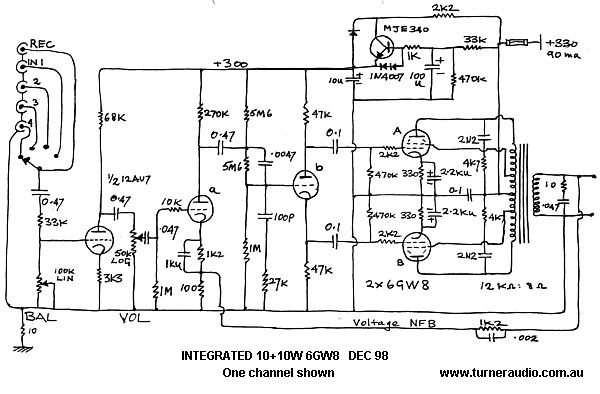
In about 1960, there was a series of "Playmaster Amplifier" amps
published in Electronics Australia magazine,
which closed down long ago. This circuit is a development of the
original and this was prepared for a client
who had a sample of one of these Playmaster amps on a very poorly
home made chassis, with lots of very
poor quality resistors and capacitors probably re-cycled from old
radios. Amazingly, it worked a bit, but with
many faults and was dangerous, and everything on top and underside
of chassis was a mess.
The existing transformers were put onto a new stereo chassis made
large enough for a source select switch,
volume and balance control. I included simple 12AX7 triode phono
stages in case he ever got a TT. The little
10-10 packs more punch than many other ten W amps, and the owner
compared it to many other big expensive
high-end amps like Krells, and found the 10-10 sounded better,
which embarrassed the owners of the big clunky
expensive stuff.
No pictures available, the project was supplied to a happy client
in 1998, well before I could type, or produce a
website. Note the transistor voltage regulator used to prevent LF
instability when the phono stage is used.
The circuit is very simple, and uses a triode gain stage for input
stage feeding concertina driver stage for the
6GW8 output tubes which have a small triode like 1/2 12AX7 plus a
power tetrode like a 6BQ5 within.
There are Ultralinear screen taps on OPT and less than 20dB
Global NFB is employed. It is a real lively fun type
of amp, and the owner says that when his wife is in the bathroom
located down a hallway,
she can hear when he plugs the amp into the system instead of the
solid state amp... "Ah," she says, "that's better."
-----------------------------------------------------------------------------------------------------
M2. Two triode phono stage with NFB eq.
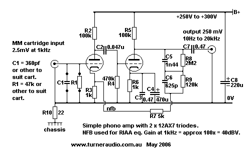
This is the simplest phono amp I know of. Where someone has a
reverse RIAA eq network and sig gene
the values of C5, C6, R8, R9 can be trimmed to get a very good
square wave at 1 kHz and a level response within
+/-1dB with sine waves between 50Hz and 16kHz. This type of phono
amp was used routinely in thousands of
phono stages fitted to budget hi-fi gear in the 1950s and 1960s.
The downside is the high output resistance of about
20k at low frequencies because there is only 6dB of NFB at 20Hz
and not much more at 50Hz so the input
resistance of anything connected after this stage needs to be
above 200k for unattenuated low bass.
----------------------------------------------------------------------------------------------------
M3. Three Triode phono amp, Passive RIAA eq.
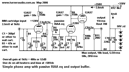
The above phono preamp schematic is designed for ease of
construction, minimize component numbers,
allow a fairly accurate RIAA eq with the aid of a reverse RIAA
network, make use of a well known common
tube type, have low distortion, a warm sound, high gain, and a low
output impedance for somebody who
may want to use it to transfer vinyl to CD or run long cables to
an integrated preamp or power amp well
away from their listening chair. What more could you want? The
calculations for passive RIAA eq are simpler
than trying to use NFB and since triode distortion and noise is
negligible at such tiny voltages involved with
a triode phono stage, then why use any NFB?
Well some people would say they want extremely low distortion,
lower than lowish. I leave the experimenter
to decide which sounds the best.
Without NFB, some care has to be taken with the power supply, and
I have shown above an absolute
minimum shunt regulation arrangement using a 10k resistor, 1 x 470
uF cap, and 3 x 75 volt x 5 watt rated
zener diodes, and I have assumed you will have a +320 volt supply
handy. Making assumptions never got me
anywhere in life, so for a basic power supply, go to Phono Amp
PSU Schematic further down this page.
The power supply shown should suffice for such a basic circuit,
with some room for use with tubes which
draw a little more anode current. Since we only want 5.2 mA of
anode current supply for 3 x 12AX7 tubes
for two channels, and then need 6 mA of current flow in the shunt
regulator zener diodes, the total anode
power will be only 11.2 mA x 320Vdc = 3.6W, using a 240 volt
secondary winding on a power transformer.
Such a power tranny would at least also have a heater winding to
provide 6.3 volts x 0.9 amps = 5.67W,
so the total power use is only 9.27 watts. In practice, we would
purchase a 30 VA transformer, because
they are likely to be more rugged. It could have a 120 volt sec,
which could be used in a doubler circuit to
make the +320 and the heater winding of at least 6.3v could be
used in a doubler as shown to make +16Vdc
at 0.45A which can be filtered down with R and C to provide a
noise free DC heater supply. A12V shunt
regulator zener diode and series diode is used to make to make
12.6Vdc and they would draw 0.3Adc.
The schematic calls for the heater supply to be biased at +50Vdc,
to relieve the pressure on insulation
between the cathode and heater in the cathode follower, only rated
for 90V.
This is easily done by making a voltage divider in the power
supply voltage output bypassed to ground
via the 100 uF, or else just taking a 100k from the top of the
first 50V zener diode to the floating heater
circuit, and bypassing to ground with 100uF. Where heater voltage
is 12.6Vdc, the lower side of the 12.6V
should be at +50V. The heater bias isn't critical, it could be
between +50Vdc and +70Vdc.
The idle current in the cathode follower buffer stage is about
0.8mAdc, not much, but even if the load on
the output is only 10k, maximum Vout > 5Vrms.
>The limit for low distortion output voltage production from a
cathode follower into a low RL is the cut off of
current in the tube. In this case when the grid voltage goes
negative enough to cut off the tube current,
the 10k ac RL and the 100k follower dc RL form a divider, and the
peak negative going voltage is limited
to [ 10k / ( 100k + 10k ) ] x Ek. Ek is the cathode idle Vdc which
will be about 90Vdc, hence the 10k peak
swing = [ 10 / 110 ] x 90 = 8.2Vpk. If output load =5k0, we could
get 4.3Vpk. Under normal use, the output
voltage won't be this high, as the average 2mVrms input from a MM
cartridge will produce an average 0.8Vrms
output. We could even afford to use a lower gain second gain tube
such as a 12AY7 or 12AT7.
If we wanted more voltage swing into a low value ac RL, we would
be better off using 1/2 12AU7 for the
cathode follower, so we could have an idle current of 4mA, and the
dc RL would be 22k, and with a 5k0
output RL, we could get a peak Vo = 18V. The gain tube before the
cathode follower could easily produce V
a up to about 45Vrms, so you won't ever overload such a preamp
with a phono signal. The output impedance
of the follower is about 700 ohms, so cable capacitance and low
input impedance will not result in high frequency
losses.
------------------------------------------------------------------------------------------------------------------------------------------------
M4. Three Triode Phono amp, RIAA eq with NFB
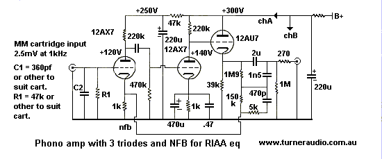
The above phono preamp schematic is virtually as simple as the two
triode phono stage with NFB eq but
has an additional cathode follower buffer output. It should sound
well. It is unknown if this topology sounds a
ny better or worse than the passive eq method, and I leave
arguments about the sound to others, but my
experience is that the NFB eq method compared to the passive eq
method can be very good indeed, if the values
of the FB network are chosen carefully, and the network doesn't
impose too low a load on the tubes driving it, e
ven at HF.
The values of R&C in the RIAA feedback network should be
trimmed with the aid of a reverse RIAA
network used to equalize the input signal in the same way as a
record cutter amp. The final buffer stage is where
the feedback take off point is for the NFB network. Any error
signal created by the following cable or impedance
will be subject to NFB correction and will have less effect than
with any other normal follower stage output stage.
A normal 1/2 12AU7 cathode follower as used in the above 3 triode
amp with passive RIAA eq will have
Rout = 600r approx. The Rout will be further reduced by the loop
NFB for the RIAA eq. The amount applied
varies with frequency and is only about 6dB at 10Hz so Rout at
10Hz at the cathode of the 12AU7 will be about
300r but at 1kHz it will be 30r and even much lower at 10kHz.
There is a slight danger that with so much NFB that HF
oscillations could be a problem if cable capacitance was high
so to safeguard the amp against any possibility of oscillation a
series R of 270 ohms is connected between the cathode
and output terminal. The 5k horizontal R in the NFB network
imposes a HF time constant well above 20 kHz to
prevent the likelihood of oscillations at HF when the cathode of
the follower becomes virtually directly connected
to the input tube cathode at HF, via the capacitors in the NFB
network. We don't need the NFB to keep increasing
above 30kHz, and we can level off the amount applied with this
trimmer resistor. It is unlikely that any recordings
have had any significant HF content added above 25 kHz, ( unless
the recording was for the short lived experiment
with quadro-phonic sound using a multiplexed signal containing a
50 kHz modulated carrier tried back in the 1970s.
Indeed the cutting head amps would have filters to prevent HF
oscillations, so if the supersonics were not emphasized,
there is no need to de-emphasize what was never emphasized. The
above amp will have less gain than the 3 triode
passive preamp, since the FB is active at LF, but still the gain
will be more than adequate for all concerned.
See power supply schematic at Phono Amp
PSU Schematic.
Note, the PSU shows simple zener diode shunt regulation of the B+.
Clever people will use a series pass
element voltage regulator to avoid any wasted B+ Idc current. I do
not have strict rules for power supplies, other
than insisting the voltage they supply be from a substantially low
impedance at low frequencies, and free of noise
from the rectifiers. I do not think paper in oil caps or chokes
must be used. Use them if you must, but modern
high value electrolytic capacitors allow RC filters to be used.
For the DIY constructor, feel free to build your supplies any way
you wish but remember phono stage amps
need well filtered supplies. I have done supplies with tube
rectifiers, tube regulators, and they can all be
made to work effectively and reliably at such low levels of power.
I quite enjoy seeing a nicely tubed power
supply for a preamp, and I have built a couple for customers on
separate chassis.
But in power amps I build, the use of tube rectifiers would cause
excessive inefficiencies, and never improve
the sound quality.
-------------------------------------------------------------------------------------------------------------------------------------------
M5. Phono amp PSU
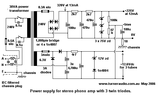
The PSU cannot be much simpler than this.
NOTE ABOUT POWER TRANSFORMERS.
You may never be able to buy suitable PT with a 240Vac HT
secondary to give B+ =300Vdc plus secondaries
for heaters for a tube preamp from your local electronics parts
dealers. But there may be someone who stocks
a suitable Hammond PT imported from Canada. RS Australia, Jaycar,
Speedy Spares, Altronics,
Wes Components may have something suitable which may be used
unconventionally.
The listed suppliers should have suitable transformers for this
method of Vdc rail production.
See Jaycar catalog number MM2004, 240V:15V, 30VA, Sec taps are at
6V, 9V, 12V and 15V. I've always found
the sec voltages are a little higher, but two such PTs would be
quite suitable.
1. Buy TWO of these trannies, and each may be priced at less than
$25.
2. Use one of them with normal mains 240V primary input. It
becomes T1.
The secondary is not grounded, as it will be biased at about
+60Vdc. From the Com to 12Vac tap you can
produce +15Vdc at 0.75Adc at a cap = 4,700uF/25V, using just one
1N5408 diode. An RC filter of 4r0 x 10W
and second C of 10,000uF/25V will reduce the Vdc to +12Vdc, with
ripple voltage < 40mVac at 50Hz.
3. Use the second transformer, it is T2, and connect its 15Vac sec
to T1 sec of 15V, so T2 is used "back to front".
There will be approximately 240Vac produced by the T2 240Vac
winding which can be used to produce up to
about +320Vdc at up to 20mAdc using a bridge rectifier with
1N5408. This 240V winding is doubly isolated
from the mains. Don't allow Idc to be higher than 20mA, which is
6.4W.
4. CHECK TOTAL POWER DRAWN. The T1 must not draw more than 30VA
from mains. There MUST be a
mains fuse before T1, I suggest 0.25Amp, slow blow type 2AG. There
must be a 3 amp slow fuse between T1
15V and T2 15V, and diode rectifier for +15Vdc must be taken off
T2 15Vac winding so if diode shorts of a cap
shorts the 3A fuse should blow. Secondary of T1 may have max loads
:-
Filaments = 12Vac x 1A = 12VA for 15Vdc at 0.8Adc.
Load due to T2 = 10VA max, so T2 240Vac current = 41mA, and max
Vdc power = 320Vdc x 30mA = 10VA.
Total loading on T1 = 22VA, allow +10% winding losses for 24.2VA
input.
Therefore T1 should be rated for 30VA at least.
5. Hopefully, you won't make clouds of smoke as the fuses should
protect you against your mistakes, which I
confidently predict that you will make. Get a tech to check out
your work before turning anything on.
-------------------------------------------------------------------------------------------------------------------------------------------------------------
M6 10 tube Preamp, April 2000
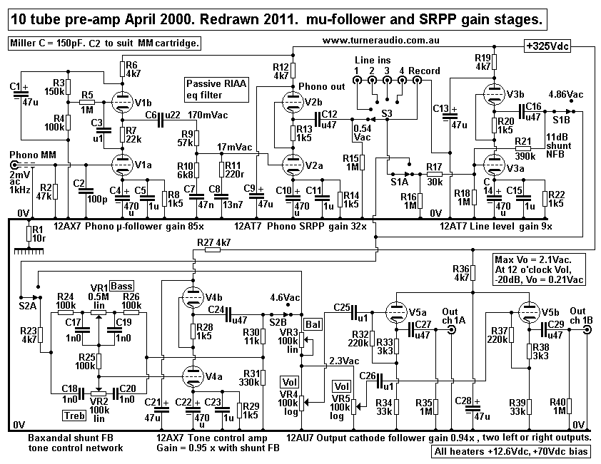
This schematic of one preamp channel was used in my own
"prototype" preamp, shown in the picture at the
Preamps1 page,
and was firmed up in April 2000. It is a good performer with phono
provision for moving magnet
phono replay. From left to right, the first tube is a 12AX7
mu-follower with gain = 88, ( 39 dB ),with a low Rout to
feed a passive RIAA filter network for vinyl use. This suits MM
cartridges with outputs down to about 1.0 mV.
Second tube is a 12AT7 SRPP to provide extra gain of 40 times ( 32
dB ) to complete the phono stage, to give a
low Rout. The gain of the phono stage is 350 times at 1 kHz, or 51
dB.
The third stage is a SRPP stage with a 12AX7 to provide deletable
tone control for high and low frequency eq.
It uses a Baxandal network in a variable shunt feedback network,
and has a gain of exactly unity, or 0.0dB.
This allows for seamless insertion into a signal path for accurate
comparison of with or without tone control.
Although tone controls have lost favor among audiophiles, they are
very useful for checking a speaker's basic
bass, mid, treble balance, and correcting some bad old recordings,
( and some lousy new ones! ).
The fourth stage is another 12AT7 SRPP stage which is also
deletable, to provide a gain of 8 times ( 18 dB ),
for the line level inputs. There is shunt feedback used to reduce
the 12AT7 gain to a sensible level, and to reduce
the Rout to feed the balance controls and a pair of dual ganged
gain pots, seen in series, which allows the tube to
see a favorable loading. The effective total line stage gain is
thus 4.5 times, (13 dB).Two switches allow or disallow
the use of tone control or line stages. In practice, both these
stages are rarely used. The fifth stage is a pair of cathode
followers using a 12AU7 which buffers the output from effects of
combined losses from interconnect cables and
any following power amp input circuit. Gain is about 0.92 times,
or -0.7 dB.
The output impedance of the preamp is thus only 600r, and it will
power any loads down to a few k ohms,
and the preamp will be compatible with any SS equipment. Both left
and right channels have two separately variable
pairs of outputs so that two systems can be set up with different
sensitivity power amplifiers to allow their comparison
at an exactly similar level of signal output. It would be easy to
use such a preamp to provide filtered outputs allowing
the use bi-amping. The phono stage input suits moving magnet type
of cartridges. The use of moving coil cartridges
would require a pre-preamp, or a step up transformer, or an
additional amp stage built into the circuit.
he 'Preamps1 page' gives recently developed details for cascode
circuitry in the phono stage using a j-fet for low level
MC inputs.
Power supply requirements
The tube line up includes Phono, 2 x 12AX7, 2 x 12AT7, Line gain,
2 x 12AT7, Tone control, 2 x 12AX7,
Buffer outputs, 2 x 12AU7. The total anode current = 25mAdc for
the 20 triodes. I use a transformer capable of
50 mAdc. The B+ supply needs to be about +340Vdc to +370Vdc, so
about 10W should be allowed for.
In my prototype, I used a separate potted B+ transformer rated for
30 VA. The heater supply for 20 triodes requires
12.6Vac x 1.5Adc, so a 30VA heater transformer must produce 12Vac
x 2.2Aac, also potted.
The TWO potted PT should be within a steel box at one end of 500mm
long chassis, far away from the phono
inputs. DIYers should allow for future changes to signal tubes
such as the 6CG7, or other octal tubes which need
twice the heater currents as the above listed tubes, so in fact
the heater current rating of the heater PT could be 3A.
If the one power transformer is chosen for all power, it should be
rated at 50VA, and be made using Bmax < 0.8
and have GOSS cores, and should be potted.
The pots do not need to be works of art metalwork, but be 0.8mm
thick mild steel sheet, and filled with 50:50 mix
of concrete made with epoxy resin and clean fine sand. I used all
DC for the heaters, and I had a LM350 regulator,
which is a TO3 device to remove the ripple from the heater
supplies after the rectifier. There were no chokes in the
preamp. The transformer heater windings, rectifiers, and regulator
are not connected to 0V directly, but are
"biased" up at +70Vdc to allow the use of the SRPP and cathode
followers without exceeding the 90Vt ratings for
the heater to cathode insulation. Then to keep hum out from stray
transformer capacitance from the mains primary,
the whole heater is bypassed to 0V with 100 uF. With signal inputs
shorted to 0V, hum in output > -0.1mV for my
prototype amp. There also has been attention paid to 0V paths in
the amp, and the schematic doesn't indicate the
optimum 0V routing. The chassis is connected directly to the earth
wire coming from the wall socket, but the 0V
line is only connected to the chassis via a 5 watt10 ohm resistor.
Thus it is difficult to get earth loop hum problems,
despite the un-balanced circuitry used throughout.
-------------------------------------------------------------------------------------------------------------------------------------------
M7. Simple phono pre-preamp using 2SK369 j-fet.
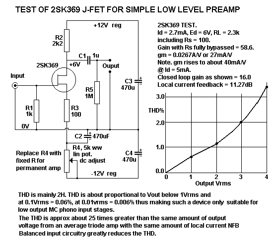
This test schematic could be used for a pre-preamp ahead of a
normal MM phono amp for MC use.
But it was used to get some idea of how linear a high gm
j-fet such as the 2SK369 (or 2SK147) really is,
and the answer is that above 0.1Vrms output the THD becomes
excessive even with nearly 12dB of NFB
applied. The THD can be reduced by near doubling of Id to 5mA,
when the gm rises to 40mA/V thus
increasing the open loop gain to 88, and thus increasing the
amount of applied NFB. The THD reduction
is only marginal and compared to a triode the j-fet has about 25
times more THD for the same Vout.
For MC use, I recommend the drain RL be reduced to 1.2k so Id
would be raised to about 5mA.
The same 100 ohms for Rs could be retained and gain overall would
then be about 9.4x which is enough
to raise the 0.3mV from a typical MC at 1 kHz to 2.9mV, with THD
less than approx 0.005%. The result
will not be as quiet as a properly made cascode circuit, but may
be quite sufficient. Output resistance will
be determined by the RL of 1.2k and noise from this R should be
just 66dB unweighted below the signal
level of 2.9mV. The fet will not have troublesome microphony that
a tube would have in this application.
However, j-fets like bjts are very prone to stray magnetic fields,
along with any input wiring.
Magnetic screening for the enclosure, well filtered rail supplies
and well routed earth paths and short leads
around above amplifiers all all essential for low hum levels. Such
pre-preamps should be set up well away
from any other equipment with a power transformer within including
innocent looking cd players and tuners
and tape decks.
Where one uses 3 x 2SK369 j-fets each with 5mA of Id the total gm
= 120mA/V. Therefore where you had
RL = 1k, the open loop gain, A, with unbypassed Rs = gm x RL =
0.12 x 1,000 = 120. If you have 100r for
Rs, then the gain with NFB , A' = A / 9 1 + [ A x ß ] ) = 120 / (
1 + [120 x 100/1,000] ) = 9.23.
NFB = about 22.7dB and THD with any phono signals will be low.
Does it sound better with 3 or more paralleled j-fets? its easy to
say that it would but who really knows?
For high gain, Rs for each of 3 j-fets can be 18 ohms for each
j-fet unbypassed from source to 0V to
eliminate the need for the negative supply so Egate can be kept at
0V bias. The separate Rs for each
j-fet source is necessary to make sure each shares the drain
current equally.
Gain will then be = 120 / ( 1 + [ 120 x 6/1,000 ] ) = 70, and only
4.6dB of NFB is involved. With higher
gain there is higher Miller capacitance. But because MC cartridges
have very low output impedance of below
50r the Miller C will not affect their output and I have placed a
whopping 0.1F across the input in parallel
with a 1k loading R for a Denon 103R cartridge and heard no HF
losses.
My CRO showed me that 0.1uF reduced the easily visible THD from a
test record above 8kHz. 0.1uF
has 80 ohms of impedance at 20kHz. If the MC cart has low Rout,
then the 0.1uF shunt C has little effect.
So a 0.3mV input signal gives 21mV output at 1kHz but remember
that at 10kHz with RIAA emphasis
there would be 12dB higher input signal so output = 84mV and THD
is a little higher but then still way
lower than what the cart gets from the record at that F. ( THD
tends to be high at higher F.....maybe
it leads to harsher sound.So hence I don't like to have the j-fets
doing very much.) The more j-fets
paralleled the less noise you are supposed to get. Noise is halved
for for each quadrupling of devices.
With x 3 devices, noise will be 1 / sq.root of 3 compared to just
one device, ie, 0.58 times less or roughly
- 4dB. This is offset by the noise of the source resistances; the
lower Rs the lower the noise.
Usually the gain x noise from the input is higher than any noise
in the drain load resistance.
I tested small signal SE BJTs in the same application and found
them all to give little better THD
measurements and the spectral content of the thd contained greater
amounts of odd numbered harmonics.
Noise was worse. And for lowest noise in a typical small TO92
package bjt the collector current is usually
about 0.2mA, so the use of 5 parallel bjts is needed to get Ic up
to 1mA, and then the maximum output
voltage is limited to 0.6mA rms, or 0.6V rms for a 1k load. BJT
Input impedance is low and the biasing
is more difficult and I just refuse to build any pre-preamps with
bjts.
------------------------------------------------------------------------------------------------------------------------------------
M8. Test filter, Reverse RIAA eq
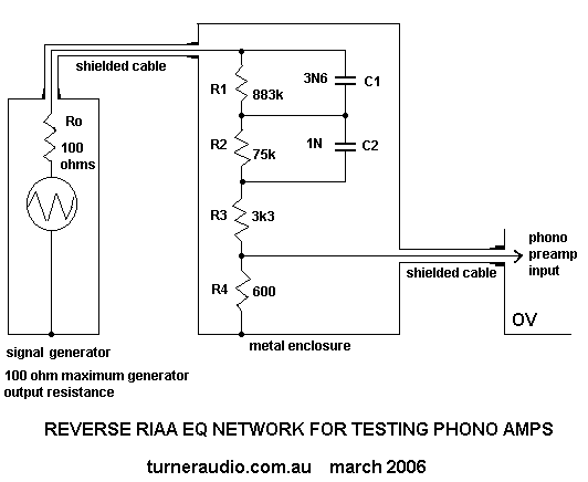
This filter is a great way to test the frequency response of a
phono amp. The filter boosts all frequencies
above very low frequencies in the same manner used during the
record cutting process. The filter profile
is equal to the RIAA profile used for all LP records. The filter
can be easily assembled on a small piece
of plastic board, and fixed to the inside of a metal container, so
that it remains well shielded, and fitted
with RCA input and output sockets. A signal generator which has at
least 100 ohms output impedance,
or lower is then connected to the filter input, and the amp to be
tested is connected to the filter output.
An oscilloscope and wide bandwidth voltmeter is placed at the
output of the phono amp being tested,
and the signal gene set for 1 kHz, and the level adjusted for a 1
Vrms output at the amp. If the RIAA filter
components in the amp are of the correct value, and have not
drifted over time, then the amplitude of all
frequencies between 100 Hz and 10 kHz should appear to be equal,
with a roll off of only 2-3 dB at 20 Hz,
and 20 kHz. The test signal should be able to be changed to
'square wave' and the output wave when the
gene frequency is 1 kHz should appear as a substantially square
wave form, without peaks or troughs along
its horizontal parts. This will show that the eq is phase correct,
and confirms the accuracy of the amplitude
response. Using a filter like this is far easier than laboriously
trying to measure the voltage output amplitudes
of test signals accurately set to spot frequencies along the audio
band. And any errors in the amplitude of
the signal gene can be neglected if the square wave test is used,
although I do like to use the sine wave test.
A signal gene with a swept frequency facility will also show the
response well. There is a more scientific
approach to reverse RIAA filters at
http://www.hagtech.com/pdf/riaa.pdf
Miscellaneous
Schematics 2
Index Page 


