OLD
RADIOS, RADIO-GRAMS.
Some pictures of BEFORE and AFTER restoration and re-engineering
work.....
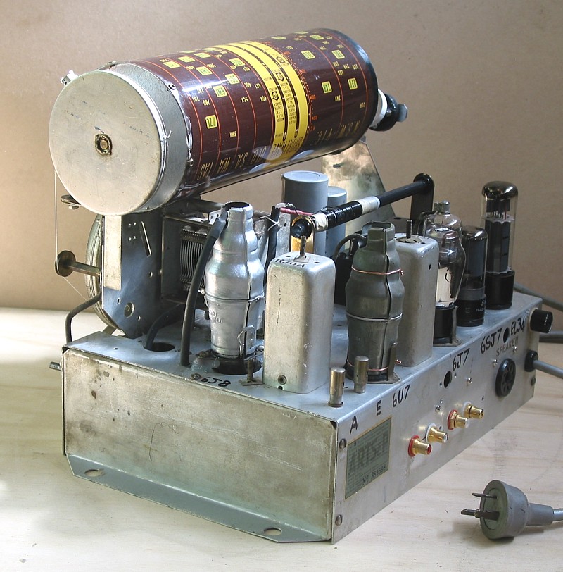
1. Healing BEFORE.
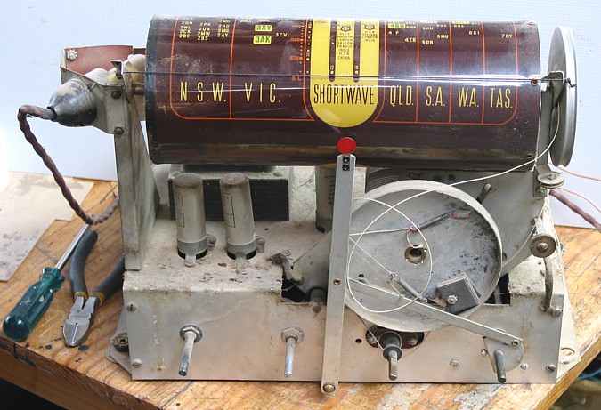
See the 15W fridge light bulb, top left, which over heated and
degraded the fragile
plastic dial drum.
Dial cord had been badly installed by earlier tech, and never
fixed, and radio was not
used for 20 years.
All old electrolytic caps were faulty, along with many other
parts.
2. Healing BEFORE.
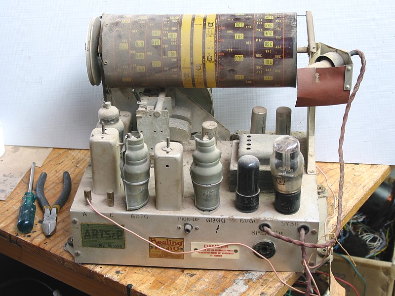
See front view of chassis, and 15W lamp is top right, and very
poor design from 1950.
3, Healing BEFORE.
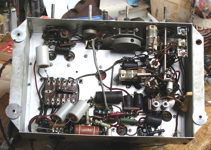
See 3 grey coloured electrolytic caps installed in 1963. The 1963
repair ticket still tied to the power cord
in 2011 listed the 3 caps and one 6U7G IF amp tube, cost was 5
pounds, about a week's average wages
equal to about $1,050 av weekly earnings in 2012 money. This
indicated the lady who owned the radio
had been ripped off badly, because the repair should have cost
$100 maximum, or 10 shillings, 10/-, in
1963 money!
Notice than many minor parts appear to be stocks from before WW2,
such as the black tubular capacitors
and all resistors.
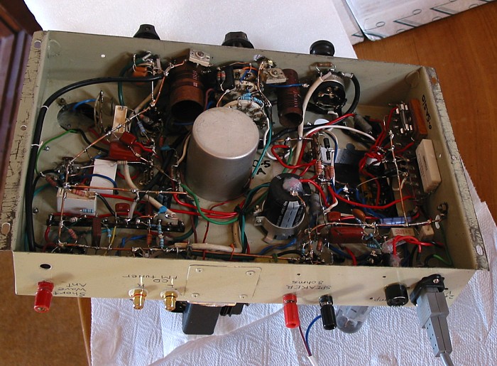
4, Healing BEFORE.
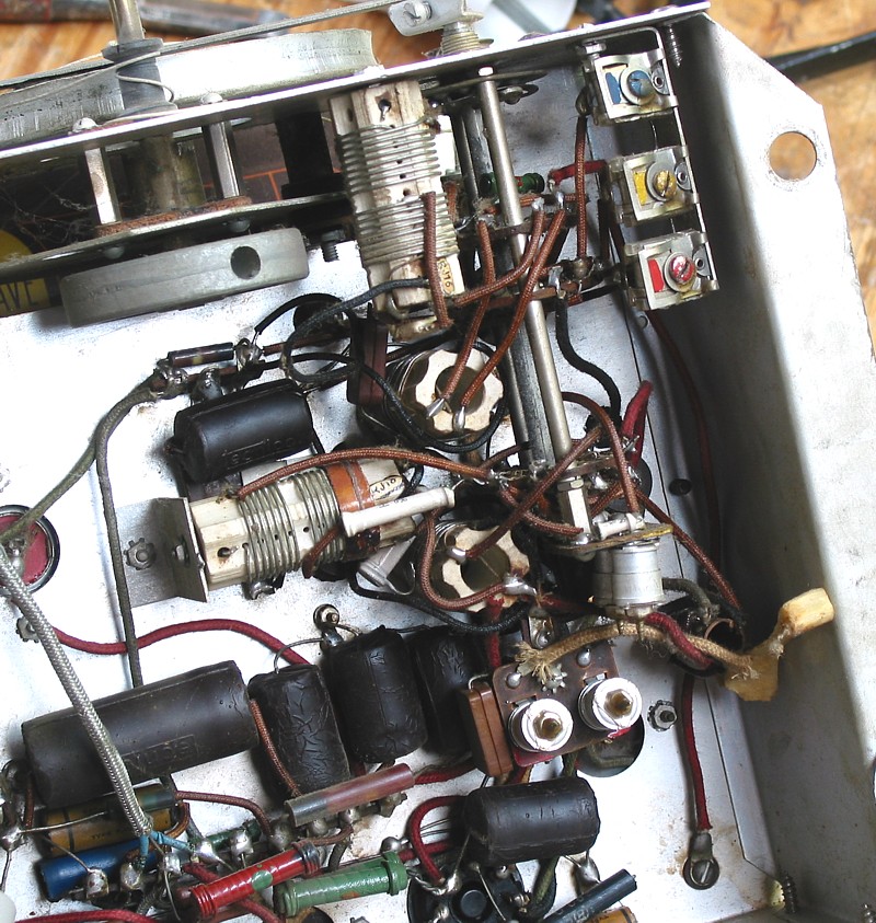
Close up of under the chassis before work. See the dial cord ran
around a rubber bush at top.
The rubber has hardened, and a deep groove had formed from dial
cord pressure over a long
time, preventing correct operation. The rubber bush was removed,
and a different shaft fitted,
giving a slower tuning rate especially useful for short wave
bands. Notice the bone to the right side,
no doubt a child had been eating a mutton chop over 50 years ago
and somehow had managed
to drop the bone which ended up wedged in under the chassis.
The radio was unaffected.
AFTER some hard work.....
5. Healing AFTER.
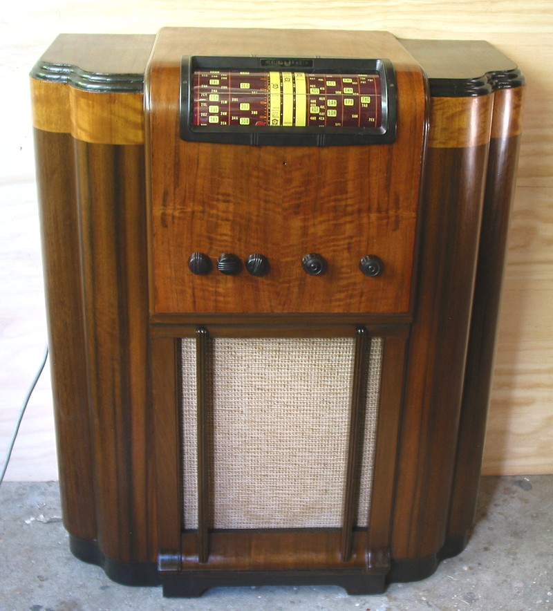
The cabinet had many unsightly blemishes. The finish was a
combination of both lacquer and french polish,
and evidence suggested the finish had been "touched up" or fiddled
with some 60 years ago.
The top of the cabinet and all brown painted edging was in poor
condition with areas of the walnut veneer
having been sanded down to paper thin to try to remove damage from
wet vases of flowers or hot objects etc.
I carefully sanded brown edgings and applied new brown paint and
re-coated with french polish.
Some carefully applied stain was applied to thin walnut veneer, 3
coats of french polish were applied all over,
and the cabinet began to look very good.
The drum dial sits behind a curved perspex guard held in place by
a bakelite escutcheon.
The old perspex had become yellowed and unclear, and was replaced
with slightly thicker plastic
obtained locally.
The escutcheon was cracked and needed re-gluing together with
epoxy and all re-fitted properly.
Different brown bakelite knobs were fitted because one was
missing, and I added a new switch.
The cloth covering the loudspeaker was very well cleaned. The
loudspeaker was in terrible condition
needing re-gluing of the cone edge to metal basket and and
re-aligning.
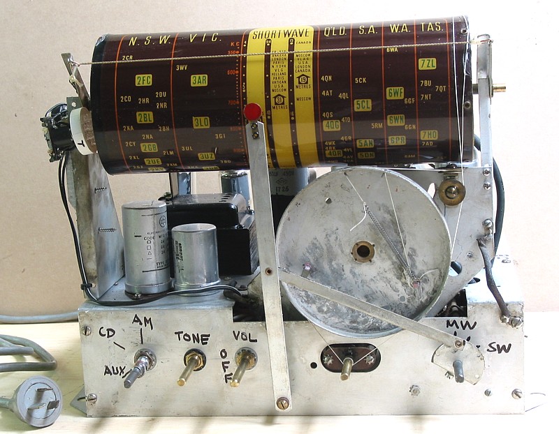
6. Healing AFTER.
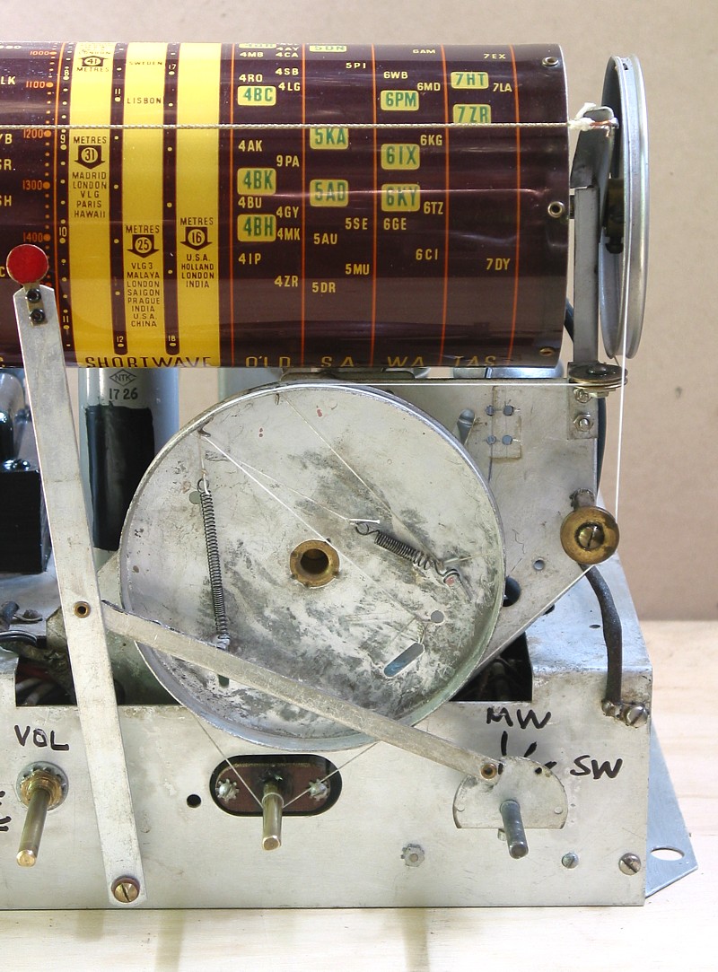
Two dial cords were used, each with its own tension spring.
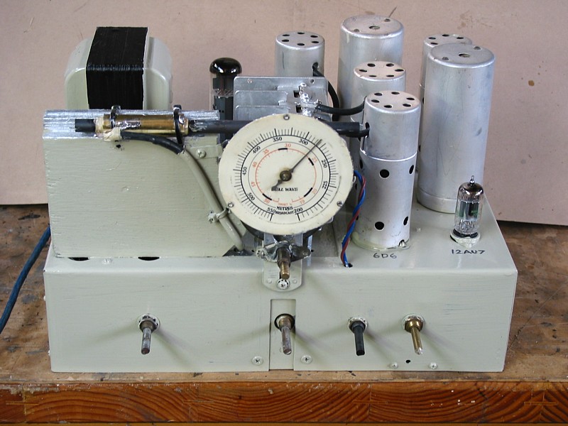
7. Healing After.
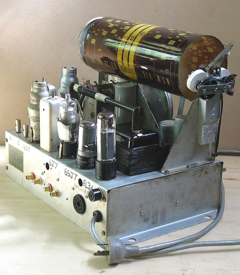
This shows two clear LED lamps to illuminate dial drum.
to left is a ferrite rod antenna and EL34, 6SJ7, 6J7.
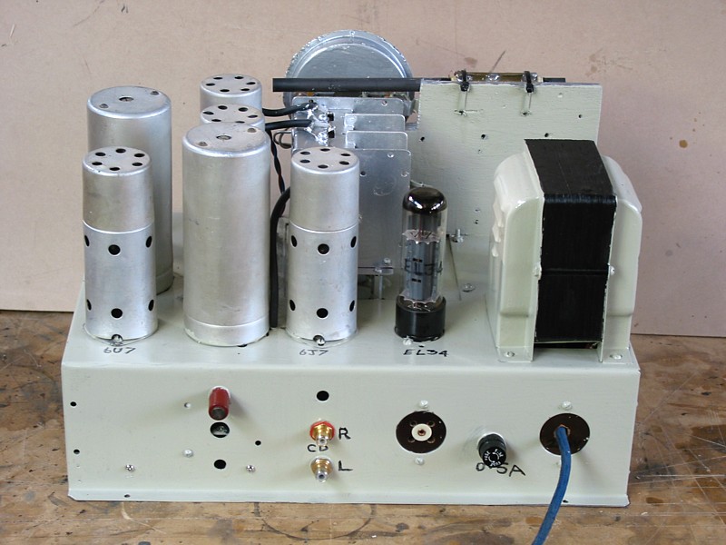
8. Healing AFTER.
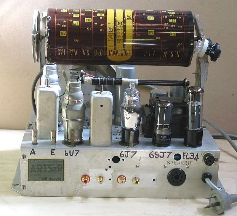
9. Healing AFTER.
This shows the repaired shielding around 6J8 and 6U7. 6J8 socket
and tuning assembly were resting on soft
rubber grommets to prevent sound from speaker causing microphonic
distortions. All grommets had perished
and become weak and brittle, so all were removed, with silicone
used as a replacement which gave the same
soft mounting. The silicone is likely to last 500 years.
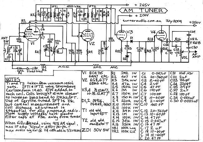
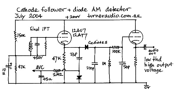
10. Healing AFTER.
Reformed Healing Audio amp Schematics :-
11. Healing, AFTER.
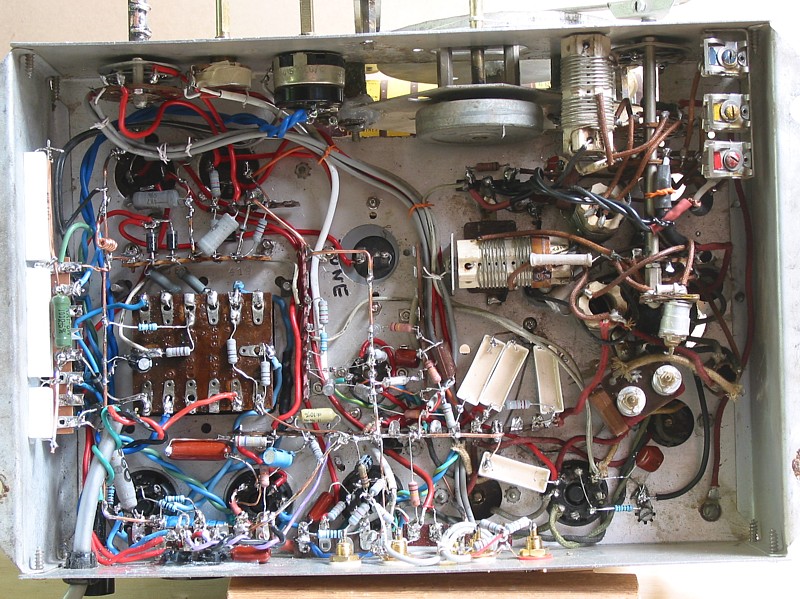
Under the chassis looks a lot different with about twice the
number of original R and C parts used for a
completely revised schematic for all except the short wave tuning
coils of the radio.
Short wave reception needed a long wire antenna, and was best if
the wire was taken up to a tree
or suitable high point.
The use of CD player or other analog stereo source gave very
pleasing mono sound.
------------------------------------------------------------------------------------------------------------------------------------------
12. Howard BEFORE.
The Howard chassis was housed in a very poor quality floor
standing timber cabinet which was
in fair condition, and not needing much work. Countless chassis
like this one were made
by many Australian or other makers and normally used for a "mantle
radio" cabinet of
small size less than a cubic foot, and such radios sat on mantle
pieces around the nation.
Today's generation doesn't know what a mantle piece is. In olden
days before gas or oil
central heating was used in houses, frozen people used coal or
wood fireplaces in their house,
and most people could only afford one fireplace, and one chimney.
And only one radio.
And often there was some sort of shelf across the top of the
fireplace front, and that's
where the "house radio" lived for 20 years. People were quite
socially skilled back in those
old days, and tried to enjoy each other's company and not fight
over radio programs or
whose turn it was to fetch more wood or coal for the fire. It
wasn't like today where ppl
huddle in bedrooms alone with a screen and the darn Internet and
fake friends on
Farcebook.
Inevitably, much larger wooden cabinets were made by eager poor
joiners to get a bigger
price from people who bought radios through such cabinet makers.
The larger cabinet
was often a 900mm high box with no back, and often was fitted with
a 200mm to 300mm
dia speaker instead of the small 100mm to 150mm dia used in mantle
sets.
This gave much better "mellow" sound, because while bass response
would extend
down to 60Hz instead of only to 150Hz, the treble remained weak
and cut off at 2.5kHz
if you were lucky.
The cabinet for the Howard was in fair condition and only the
chassis was brought to me
for repair. There was a huge long list of problems and a total
re-build took weeks.
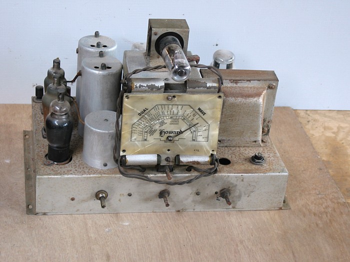
13. Howard BEFORE.
2 tubes on left were original queer European types with unusual
recessed sockets with
4Vac heaters. Replacements were not available. 2 other tubes had
obviously been changed
from Euro to "normal" octal and a small additional 6.3 Vac
transformer added, maybe in
1955. The dial mechanism was the old metal disc and pinch wheel
type which failed to work
properly since about 1960. The dial itself had missing bolts and
plastic was shabby.
There were many things wrong everywhere with everything in this
radio chassis.
The chassis is steel, but not plated, and the single coat of paint
was powdery and allowing
rust everywhere.
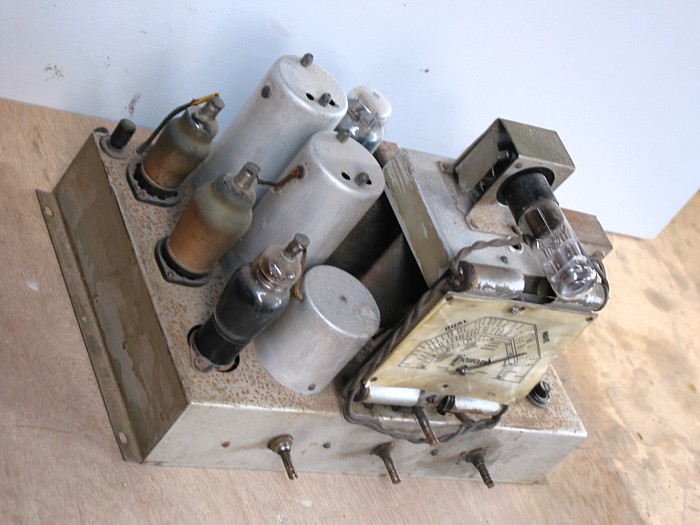
14. Howard BEFORE.
The set had been repaired sometime after 2005, and some capacitors
were replaced.
The set had given some sound for awhile, very quiet, lots of
distortion, then died.
Ah, the Unknown Stupid Bastard has struck again! ( USB ) All the
big problems with
so many things had not been fixed.
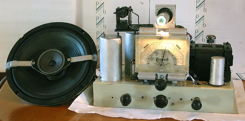
15. Howard, AFTER.
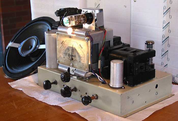
The chassis looked better with set turned on than the photo shows.
The whole dial assembly
was re-engineered to have a dial cord and drum tuning. Magic eye
tuning now works.
The old 10" speaker and its output transformer were beyond repair,
and replaced with a
10" hi-fi speaker I had "laying around". To increase the speaker
bandwidth from the original
2.5kHz, a 2.5" dome tweeter was fixed on aluminium straps bolted
to edges of the 10" basket.
The 1995 10" speaker had the same overall size and bolt hole
spacing as the original from
1945, so the owner would have no trouble re-installing the speaker
without cutting an extra
hole in the cabinet front for a tweeter. Thus the speaker was able
to reproduce high frequency
sound from CD or other source from rear RCA terminals.
Bass from such a speaker mounted in a large floor standing cabinet
without any back extends
down to about 60Hz and usually quite pleasing for most music.
16. Howard AFTER.
The photo shows the dial brightness more than what it really is.
It looked just though when
fitted to the cabinet.
17. Howard, AFTER.
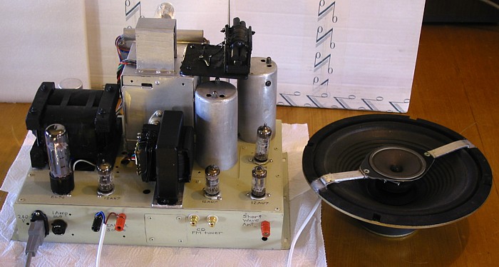
Rear view of chassis and with speaker and its two terminals.
RCA sockets for left and right output from CD player mono sound.
18. Howard, AFTER.
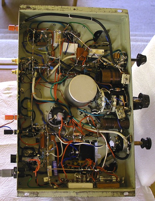
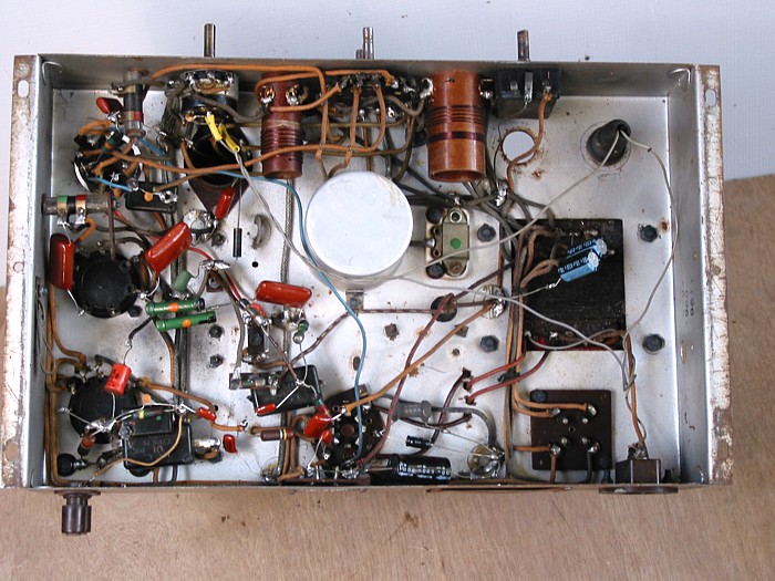
19. Howard, AFTER.
Under the chassis is completely rewired with my own unique
circuit. It has more than
twice the number of R + C parts, but all are needed to get the
quality Mr Howard left out
back in 1938 because it may have been Too Hard.
Sound quality is now fabulous!
----------------------------------------------------------------------------------------------------------------------------------------
ADRIAN'S OCEANIC.
This chassis had a nice big timber floor standing cabinet which
did not need any work, except that
the cheap pink cloth used in front of the speaker looked quite
odd. The owner wanted it to stay that
way, so it was. The chassis was a rusted mess, needing weeks of
work totally re-building it all.
20. Oceanic, AFTER.
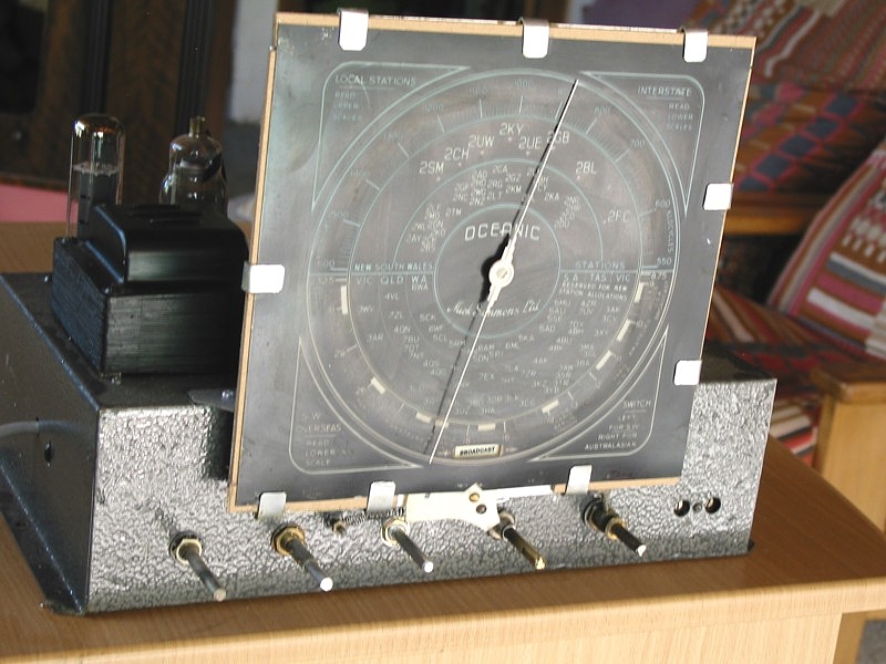
The nice big dial is some sort of fragile early plastic and the
translucent paint on the rear of plastic
had been touched up by someone badly and any attempt to make it
look better at night would have
ruined it, so all I could do was clean and re-assemble it all and
place metal clips to hold the warped plastic to its
steel frame. Clips remain hidden when chassis is in cabinet.
Chassis was sanded clean inside and out and
given a coat of of "crackle tone" paint.
21. Oceanic, AFTER.
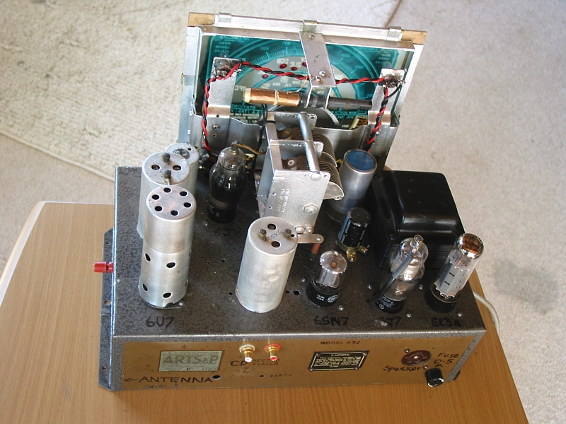
The set has 6J8 mixer, 6U7 IF amp, 6SN7 AF detector, 6J7 audio
driver tube, and EL34 output tube in
triode mode I added a ferrite rod antenna for local AM and the red
terminal at LH side is for a SW
long wire antenna. Mains transformer was removed, varnished,
replaced, and painted black.
22. Oceanic, AFTER.
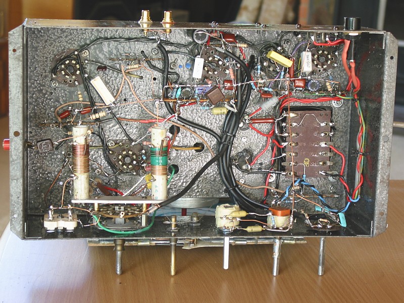
The circuit was completely re-designed and re-wired and included
one extra switch added to allow
any modern stereo source signal such as from a CD player,
cassette, or phono signal if amplified to
line levels. Much old radio wiring was done using cloth covered
rubber insulated stranded wire and
the insulation disintegrates and there is risk of short circuits
and damaged parts in future. Therefore
PVC insulated wire was used for re-wiring.
The original set was made sometime between 1939 and 1950.
It was used in a large timber floor standing cabinet, and its
sound quality would have always been
dreadful, but now it performs beautifully.
-------------------------------------------------------------------------------------------------------------------------------------
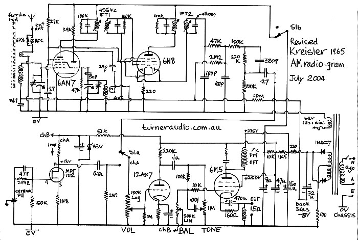
TREVOR'S RADIO. I don't have any BEFORE pictures for the next
radio set which had no brand name
anywhere on the chassis or its floor standing cabinet which was
yet another low grade type.
The chassis was a fair old mess, and all required a total re-build
with better circuit.
An enormous number of hours were spent, as usual.
23. Trevor's radio chassis AFTER.
There is now a long ferrite rod for local AM stations, and wires
are shielded where possible, even with
a brass shield around the coil on the rod. Such tight shields are
kept 2mm away from coil, and have a
gap so they do not form a shorted turn, but act to shield the coil
from electrostatic pick up, but while
allowing the magnetic portion of electro-magnetic radio wave to be
picked up without so much noise
from modern devices and fluorescent lamps. Chassis was fully
re-painted, timber block used for ferrite
rod support, dial mechanism re-made. Black control shaft at front
is for switching to CD or other source.
After stripping the whole steel chassis bare it was sanded well
and repainted with oil based paint,
a pleasant pale green-grey. The chassis top has an L shaped piece
of flat colourbond sheet metal
siliconed and pop riveted to the painted chassis to hide all old
tube socket holes. The type 80
rectifier tube was replaced with silicon diodes - normal practice
for me. The EL34 on left is
used as a triode for 5 good watts to power the new speaker through
a new output transformer at
bottom centre. I wound this OPT. The original audio output tube
might have made 2 watts,
OK for the old speaker when it was new, but the new speaker needs
more power.
I also fitted a new power transformer. Other new replacement tubes
were 6AN7 mixer,
hidden from view at far top right, then 6N8 IF amp, AF 12AU7
detector, 12AU7 AF pre-amp
and tone control, 12AX7 AF amp input/driver for EL34.
24. Trevor's radio chassis AFTER.
The chassis rear shows new mains cable and mains fuse. I always
use a 3 wire mains cable and always
connect the chassis to Earth via green-yellow wire. External sound
source such as CD player can be
plugged in at the RCA terminals. I would guess this radio chassis
was originally bought by a late1930s
furniture maker who could sell his cabinet work with the radio
inside and get more income.
The floor standing cabinet for this radio chassis was of minimal
size, with cheap plywood stained
dark, and with a small round port hole for the dial. So such a
radio could never be a high value
collector's item. But it performs so much better than many better
looking floor stander radios held by
collectors.
----------------------------------------------------------------------------------------------------------------------
Other miscellaneous AM radio schematics :-
There is a lot more about AM radio circuitry for AM Hi-Fi
performance at
my page on Kitchen Radio 2015.
-----------------------------------------------------------------------------------------------------------------------
The range of 10 AM radio stations which some of my customers
listen to in Canberra :-
My irrational horrible scores out of 10 for listenability
factor.....
666kHz, Triple 6, local ABC Canberra. Local content, rather
boring, parochial, too much sport,
too much old fart chat about flippant issues. 4/10
846kHz ,ABC Radio National. Many interesting discussion
programs, some world music.
It is worth having a good AM radio for this station alone. 10/10
1008kHz Horse Racing. I don't bet on horses, and hi-fi is not
needed. -1/10
1053kHz, 2CA, Boring repeated replay of a small number of old
hit records, boring advertising. 1/10
1125kHz, Radio 1RPH, Radio Print Handicapped Network. Good to
listen to news papers
being read, some book reads, dramas, announcers have foggy old
voices and cater for
mainly older people with impaired senses who have fond memories
of the heyday of radio
between 1935 and 1955, especially including WW2. I have enough
compassion for other
less well off than myself to give it a high score, 9/10.
There is little advertising, and although signal is only 300W at
transmitter, sound quality is
good like ABC Radio National, because RPH caters for those who
cannot read, so a radio
gives them their world.
1206kHz, 2CC – Capital Radio Network, Boring repeated replay of
a small number of old hit
records. Red-neck talk back, unintelligent BS most days,
advertising. 1/10
1323kHz, Country music, no need for hi-fi. Not my scene to
listen
to crap songs about achy breaky hearts and being lonesome by Oz
singers with false US
accents. 1/10
1440kHz, SBS Radio Multicultural, Mainly Chinese language
broadcasts with small
music content.
Excellent for those multicultural type who enjoy music with
their own languages 8/10
1620kHz, Italian Radio – Sth Canberra. Italian language
broadcast 5/10
1629kHz, Rete Italia, Italian Radio – Nth Canberra. Italian
language broadcast 5/10
Issa notta too badda. Summa time they havva de Tarantella, we
canna be 'appy.
I find I like ABC Radio National during breakfast, lunch,
dinner, and during coffee breaks.
But not all ABC talk subjects interest me and a quick tune along
the band reveals nothing
anywhere worth a listen so I will then switch to ABC Classic FM
102.3Mhz, or the news station
on 103.9Mhz.
My own AM kitchen radio which I built from scratch in 1999 does
not pick up FM. But I have a
1975 Audio Reflex AM-FM tuner from about 1975 sitting on top of
the timber tube radio cabinet,
about 450mm wide, 250mm high, and 250 front to back. This allows
hi-fi mono FM, and the
tubes do the AM. See Kitchen
radio 2015.
Sometimes nothing is interesting on radio, so I hit the off
button. But most days radio is an
important source of music and info, and I'd have a much poorer
life without radio broadcasting.
Without broadcasting, you have to spend time searching for
interesting media content elsewhere,
and radio allows highly trained people to do your searching for
you, and with music they will
often make far better choices than you or me.
____________________________________________________________________________
Some customers I've had wanted their old equipment fully
restored to its original condition
without changes to the original appearance of perhaps 70 years
ago. Much ancient electronic
equipment comes to me in a terribly unsafe condition. I will
always try to fit modern safe mains
wiring and a fuse so that ancient equipment won't give you a
shock, electrocute your cat or
burn down your house, so the mains cabling may change slightly.
Full restoration is more expensive than providing the minimal
repair of the equipment to make
it work. Restoring the appearance may cost much more than the
electronic restoration.
I know furniture restoration tradesmen who can do french
polishing and veneer repairs.
Their cost usually exceeds mine for any large mantle radio or
larger floor standing radio or
radio-gram.
Modern polyurethane finishes are not much cheaper but I am well
skilled at this, and cheaper
than the specialists.
Polyurethane varnish is more rugged than french polish shellac.
For any given amplifier, pair of speakers or old radio, there
may be a need to replace any old
parts including switches, mains cabling, volume & tone
controls, dial tuning assemblies,
electrolytic and paper+foil capacitors, resistors, tube sockets,
tubes etc which may threaten
the the future reliability of the item or become dangerous. The
repair has to include preventative
work to ensure a happy future. So when I repair an old 1950 tube
amp or radio, I don't just
replace one little part, leaving many others which will fail
sooner rather than later.
Usually many parts need replacing to get low noise and low
distortion giving good
performance of the unit to meet modern expectations of sound
quality and reliability.
I am well skilled at designing amps and radios to give
better-than-original performance but it
does take a lot of time, and any time you contact me I am likely
to have many months of work
ahead of me.
Old radios, and radiograms have been a small part of my work,
but much care is taken to ensure
such old items benefit from restoration for future generations
to enjoy.
_____________________________________________________________________________
Canberra's FM radio stations. This time I won't be an old
curmudgeon and award points out of 10.
Note, repeater stations are for Tuggeranong
87.6MHz, Raw FM. Need to be desperate to listen
87.8MHz, Student. I never listen, sum wun duz, dunno hoo.
88.0MHz, Spanish. have not heard it often.
88.7MHz, Horse Racing. I never bet.
89.5MHz, Community, but I was never drawn to it as being
interesting.
91.1MHz, Multicultural Radio, in foreign languages.
91.9MHz, Canberra Christian Radio Limited.
94.3MHz, repeater, CCRL. Try as they mite, I just cannot believe
a word they preach.
Just be good, OK. No need to involve any God.
92.7MHz, Arts FM, Music and arts. Not totally crook, but lacks
good announcers, and has too
many adds, with dis-jointed choices of music.
ABC classic FM is 1,000% better.
90.3MHz, Arts FM repeater.
96.7MHz, QBN FM – Community radio, maybe OK.
97.5MHz, Hot Country Radio. Country achy breaky hearts.
98.3MHz, 2XXFM, Community radio, sometimes OK, but so much
noise.
101.5MHz, Triple J, ABC run for puerile ppl with immature
musical taste, Boom chikka boom etc.
95.9MHz, Triple J repeater.
102.3MHz, ABC Classic FM. Great variety of classical music
written before most pop music started.
Has too many film sound tracks now, plus too many old favourites
too often.
Victim of Liberals who hate ABC. Is so good though, worth owning
FM tuner to receive it.
99.1MHz, Classic FM repeater.
103.9MHz, ABC News Radio. Good for repeated news, sometimes BBC.
99.9MHz, ABC News Radio repeater.
104.7MHz, 104.7FM, pop music.
100.7MHz, 104.7FM repeater.
105.5MHz, SBS Radio, Multicultural.
106.3MHz, Mix 106.3, pop music.
107.1MHz, Mix 106.3 repeater.
DAB+??? :-
SBS Radio SBS Chill
SBS Radio
SBS PopAsia
Hot Country
My Canberra Digital
Radar (radio)Southern Cross Austereo
Mix 106.3.
Digital radio cannot be received by circuits above and needs
highly hugely complex
miniaturised IC circuits that nobody is allowed to know about.
Most DAB, Digital Audio Broadcasting stations just have content
of associated FN stations.
To
Index Page