Kitchen AM Radio 2015.
This page is about how to get best sounding AM radio reception of strong local radio stations.
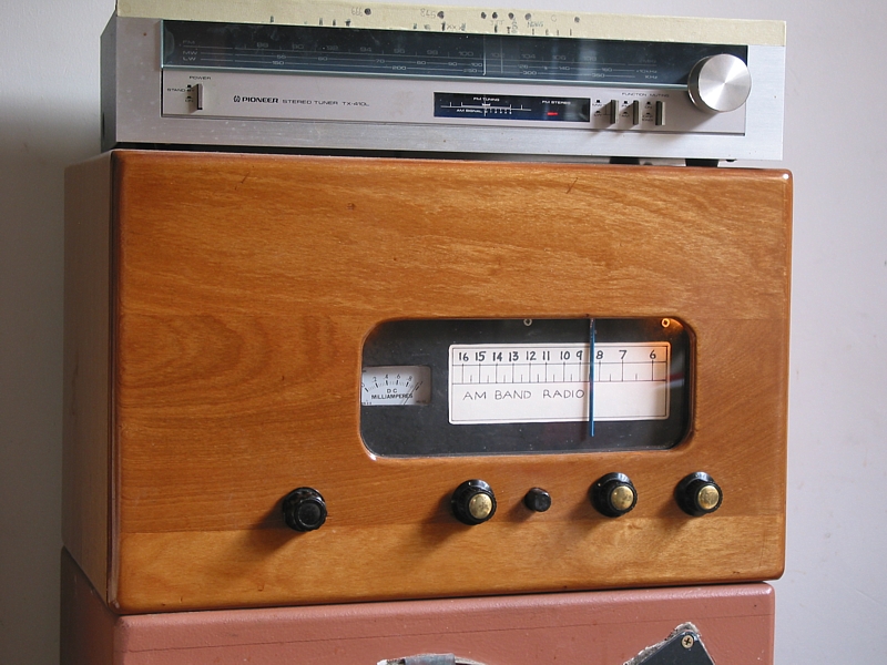
Fig 1. Kitchen Radio, 2015.
Kitchen-Radio-front-2015.jpg
The plywood box has the tubed AM radio circuit.
There is a 1970s generic Pioneer AM-FM tuner sitting on top of radio, replaced in 2017 with a better Audio Reflex
AM-FM tuner. This AM-FM tuner is only used to provide mono FM sound.

The AM radio has a single EL34 in triode for 5W which makes fine music for the 80 litre speaker box on floor. The dial
mechanism uses a sliding pointer along a bar with a dial cord & wheel on the capacitor tuning gangs. The tuning meter
was recently made in Taiwan in about 1993. Box was made from material from a 1950s radio-gram.

I built this radio in 1999. I had been fixing old radios and guitar amps since 1993, and I didn't need to try to find enough
spare parts, aka old junk to build a complete radio. The junk seemed to just grow because ppl donated what they didn't
want, or they didn't want to fund the repairs. I first tried to build a synchronous AM radio similar to the design by
Mr D.G.Tucker published in 1947 copy of Wireless World magazine. This respected UK magazine had numerous
articles on radio and audio and is very good reading for anyone interested in electronics before 1960.

Tucker's "Synchrodyne" used used mainly pentodes and while I should have succeeded, I found several aspects too
difficult to make or understand, and I realized a well done "superhet" circuit would be be easier and better for
reception of strong local stations.

By 1999 I thought a good superhet needed a different approach to what one finds in nearly every AM set,
a bunch parts which have been designed by greedy company CEOs and their accountants. All the many mass
manufactured AM sets I have ever repaired had disappointing performance including spurious noise, hum, high levels
of THD + IMD, and limited RF bandwidth, and were prone to noise from countless devices such as compact
fluorescent lamps, phone answering machines, and many other things which slipped past all the regulatory authority
rules on RFI.

The 80L ported bass reflex speaker has 1953 300mm "Rola Deluxe" driver and a 1974 Foster 25mm dome tweeter.
The two units produce a flat response with crossover at 4kHz; the old Rola had sensitivity over 95dB / W and could
reach 5kHz without typical cone break up mode uneven response. So no need for a 3 way speaker system.
The Rola worked well with a reflex box with ports, but bass below 70Hz was down so the crossover includes a series
network with L // 8r0 which reduced all above 70Hz by 4dB and extended bass response to 40Hz. I ended up with
sensitivity of 92dB and response 40Hz to 15kHz. There is plenty of low bass in much music and I wanted to hear
 it all. The overall result sounds natural, with warm midrange and clear treble free of sibilance.

Controls are all MANUAL but within easy arm reach from kitchen table where I spend time for meals, thinking
and diary writing. This habit of life in a kitchen is a highly specialized anti-marriage technique, a pity really, but if
any sheila spent longer than a minute in close proximity she'd be thinking of "makeovers" including banishment of
man + junk from kitchen. ( Why can't women just sit and listen and think? )

It is only mono channel sound - quite OK for a kitchen. AM comes from the tubed tuner and FM from the Pioneer
AM-FM tuner. The Pioneer is supposed to give good FM but in fact I find it sounded dull / honky compared to AM.
I can switch between the same ABC networked broadcast news from AM Radio National 846kHz to Classic FM
and the AM always sounds crisper - cleaner and "less boxed". I have to turn up the treble FM, although tests revealed
FM tuner did have AF response to 16kHz, -3dB. I found treble boost or cut above 2kHz was essential because it
seems the FM or AM transmitted has much varying levels of treble. But I've found +/= 6dB boost or cut is enough.
The AM source from Pioneer tuner is nowhere near as good as my tubed AM tuner.
The Pioneer eventually stopped working so I replaced it with a better Audio Reflex, also from 1970s.

I have reasonably good AGC control for some locals here such as print handicapped station RPH at 1,125kHz.
It is usually a good quality signal but its only 300W, while other stations nearby are 5kW, such as ABC Radio
National 846kHz.

To get away from the normal old radio sound I used :-

A. Ferrite rod antenna with a single tapped winding, Q < 35, which tracks well to the oscillator tuned LC, and
which picks up magnetic part of radio signal, not the electrostatic part which includes so much noise from compact
 fluorescent lamps etc. ( The alternative to a ferrite rod antenna is the shielded loop and they are good, but you
need room for them. )

B. 6N8 pentode for input RF amp with AGC voltage applied for auto volume control.

C. 6AN7 frequency converter, a well known reliable tube, with partial AGC applied. D. Modified IF transformers
made originally in about 1950, for wider pass band, while retaining "skirt" selectivity.

E. 6BX6 "sharp cut off pentode" for linear IF amp without AGC.

D. 12AU7 cathode follower for linear low Z drive to diode + C + R AF detector followed by RC ripple filter,
with output follower to reduce audio THD / IMD > 0.5% for 85% modulation and negligible for 0% to 30%
modulation which has the majority of the dynamic range broadcast. This assumes IF carrier level applied to
detector is between 4Vpk and 8Vpk.

F. Two pairs of L+R RCA terminals for selectable external audio inputs from FM tuner, radio gram, CD, i-pod, etc.

G. Line level preamp with variable shunt NFB to equalize levels of all sources.

H. Passive treble control to boost or cut F above 2kHz to max of +/- 6dB at 10kHz.

I. EL34 in triode for SE amp to make W max, THD < 1%, allowing use of any available wide bandwidth hi-fi speaker.

H. Heavy hi-fi speaker to support radio set, and which does not color sound, in a separate cabinet so audio vibrations
cannot cause microphony with tubes.

I. PSU with high value electrolytic C and Si diodes, and more bypassing of B+ and B- rails for total noise free operation.

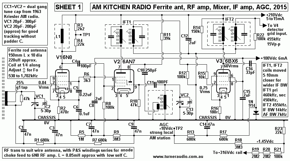
SHEET 1. Kitchen AM radio, RF, Mixer, IF.
Kitchen-AM-radio-schem1-RFA+IFA-2015.gif
RF input is generated from a ferrite rod antenna. This produces much lower signal level than the old fashioned RFT
normally fitted to most older sets which needed an antenna which was at least a 3 meter length of wire to a curtain
rod at a window. The ferrite rod antenna picks up the magnetic portion of the radio wave which has much less
lectrostatic noise than when using a wire antenna.

The Q of the ferrite antenna is high, over 50 is possible, so that RF bandwidth at 550kHz is 11kHz, which means audio
BW could only be 5.5kHz if the following IF bandwidth was wider. I found best operation was with slight Q reduction
with 47k R loading across the ferrite LC. Resulting LC bandwidth is 20kHz minimum at 550kHz for a resulting Q = 27.5.

I've often used a ferrite rod antenna to replace the small RF input transformers in old sets which only suited a wire antenna.
I'd buy a bare rod, still available in 2015, either 150mm or 100mm long, and wind a coil with about 50 turns of solid
Cu wire from Cat-5 cable. This 0.5mm dia wire has about 0.25mm polythene insulation, and Q can easily be over 50
at 550kHz, and coil self C < 5pF. The coil turns depend on amount of inductance wanted to suit the tuning gang
capacitance. Many old sets have tuning C = 5pF to 440pF.  A rod antenna has its coil usually set at 1/3 the way along
the rod which allows coil to be moved further towards a rod end or to center so allowing inductance to be varied for
best tuning at the low end of AM band with tuning cap maximally meshed. With that done, tuning at high end of band
is done with trimmer C across tuning C which is fully open.

If C max with tuner C plus a trimmer C = 460pF, the theoretical L in mH needed may be calculated :-
L = 25.35 / ( MHz squared x CpF )
For 530kHz, and 440pF,
L = 25.35 / ( 0.53 x 0.53 x 440 ) = 0.202mH, ( or 202uH ).
The coil can be on a cardboard former able to slide along rod to change L value about +/- 30%. This range is seldom needed.
A coil position is found tuning F = 530kHz when tuning C is maximum at say 460pF.

Within the 50 turns, a tap for grid is at about 13 turns away from the earthy end of coil. The wires from tap to grid and from
live end of coil to tuning gang must be less than 70mm so they do not act as wire antennas. The grid tap has low output
impedance and the tube input capacitance does not react with coil to limit HF tuning.

The rod+coil should be able to be tuned across a range of 531kHz to 1.720MHz. The ratio of HF : LF = 3.24 :1.
The theoretical C minimum to get to 1.72Mhz is 43pF, comprising the minimum C of tuning gang + trimmer
C + coil self C + any stray C between wires and chassis.
Not all AM radios achieve this range of F because the total minimum C across the coil is much more than I say is possible
here. I found many older sets could only manage 550kHz to 1.5MHz. This didn't bother many ppl because most AM
stations are within this reduced band. But if you lived where your favorite was at 1.6MHz, then you would be disappointed.

The LC Q reduces as the F increases for the high end of the AM band. This is OK because the purpose of the LC input
coil is to give MODERATE selectivity so that a 5kW station does not overload a mixer causing "cross modulation"
interference when listening to a 300W station only 45kHz away. There could be more than one ferrite rod+coil arranged to
point in different directions to favor one wanted station, but the operation becomes difficult for anyone to get right and
benefits are few. Ferrite rods are directional, and like AM loop antennas, should be able to rotated in a horizontal plane
at least 90 degrees. Usually a position can be found to favor most stations.

The low RF signal from my ferrite rod LC means a following RF amp is needed. I chose a mini 9 pin tube 6N8 remote
cut off pentode with AGC applied to vary its gain for automatic volume control. The 6N8 boosts the RF to be applied
to a triode-heptode 6AN7 frequency converter (aka mixer ). 6AN7 anode output feeds IFT1 primary, and IFT1 sec feeds
a 6BX6/EF80 sharp cut off pentode IF amp which feeds IFT2 primary. IFT2 sec feeds the detector circuit on SHEET 3.

There should be a future supply of these 3 tube types which were made in huge numbers until about 1970.
The 6N8 was chosen because I have a few, and is suitable for gain control with AGC voltage. Its two diodes are
normally used in an IF amp stage to generate AGC Vdc, but are not used here. A good alternative to 6N8 is 7pin
6BA6 remote cut off pentode.

V1 6N8 anode is fed through an untuned choke L1 which is a spare old input RFT normally used for for a wire
antenna, arranged with pri and sec in series to make an "informal choke" of about 0.85mH, and with low C and
high enough self resonant Fo.
Such a choke has reactance of 2k9 at 550kHz, rising to a peak at about 1.4MHz due to its self resonance.
The R3 2k2 R4 22k across L1 allow viewing V1 performance on a CRO with low input C probe without affecting
V1 performance.

With no tuned LC in V1 anode circuit there is no further RF bandwidth reduction and all following selectivity is
due to the two IFTs. The gain of V1 is quite low because it spends most of its time with AGC about -3Vdc with
strong local stations which keep gm low for low gain. V1 also has unbypassed Rk 470r. The overall effect is that
very low power local stations of 300Watts generate low AGC to get V1 to have maximum gain, so their sound
level is only slightly lower than strong stations, needing a small increase of volume control.

V2 6AN7 triode-hexode is my favourite 1960s frequency converter. The cathode is common for both tube
sections and connected to 0V. The triode acts with an oscillator transformer with tuned grid LC which generates
a huge 40Vrms with negative Vdc bias generated by C11+R10 which stabilizes the oscillator level. The triode grid
feeds grid 3 in hexode by internal connection. The triode anode powers the grid coil via an untuned anode coil with
less turns than grid coil.

The hexode is thus being turned on and off by the oscillator signal. The hexode operates as a non linear amp
with dual grid grid inputs, and interaction due to capacitance between the two two inputs is avoided by having
two screen grids.

Any RF input to hexode g1 pin 2 produces a number of intermodulation harmonic products in the heptode anode
current. The anode Ra is fairly high. An oscilloscope will show hexode anode voltage at IFT1 primary to be mainly
the oscillator frequency in addition to a blur of other frequencies. The IFT1 LC has its highest tuned Z at 455kHz,
and all F away from 455kHz are shunted by L or C. The magnetic field changes mostly at the tuned 455kHz,
so output from the IFT1 secondary shows mainly only 455kHz.

The oscillator is arranged to always run at 455kHz above the tuned F for the input RFT with rod+coil and tuning gang.
So if RF input range is 530kHz to 1,730kHz, oscillator moves from 985kHz to 2,185kHz, a ratio of 2.22, a lower F
range change which should be easy to get by using just the right value of fixed C in series with a tuning gang identical to
that for the input RF LC.
In my radio, I have a fairly miniature Kriesler brand two gang tuning C made in about 1965 to suit the last of the tube
sets and beginning of SS circuits. The oscillator gang has smaller moving plates to produce a smaller C change
and to give oscillator F which is more likely to always be 455kHz above the RF input. Kreisler saved the 10c cost of
1 series C. Often the sets with identical C gangs had a series C which changed its C slightly with temperature to compensate
for tuning drift as the whole set warmed up from say 15C to say 40C inside the box. Such a C is not essential.

The action of having oscillator F always being 455kHz above input RF is called "tracking" and in practice it is
impossible to get perfect tracking when using identical tuning gangs and a fixed C in series with oscillator gang. RDH4
explains it all better than I have room for here. Kreisler probably used the non identical tuning gangs to get better
tracking, but I have never been sure they achieved that goal.

Alignment of this type of radio, calibration of dial.....
Gear needed :- Oscilloscope, RF signal gene with Ro 50r and for 455kHz to 1.75MHz at least and with adjustable
AM modulation between 0% and 100%, with envelope THD < 1% at 90% mod.

Digital frequency meter. Voltmeters. Screw driver with plastic or wood shaft with small metal end bit for adjusting
IFT screws to move ferrite cores. Screwdrivers must have no effect on C or L of the LC coils.

External PSU with Ro < 1k0, and with adjustable Vo for -10Vdc. Several 300mm leads of insulated wire with alligator
clip at each end. Leads to bring test signals to points on RF and IF circuits.

1. Turn on radio, wait until set is warm after at least 15 minutes. Spend this time checking Vdc and Idc around the
circuitry.

2. Connect DMM to read Vdc at TP2. The aim is to adjust 2 tuned LC in each IFT to get wanted band pass shape.
Connect short lead with alligator clips across 47k at ferrite rod input.
Connect oscilloscope to output of AF detector at V4b cathode. Turn volume control low.

Connect low level 455kHz signal without mod to anode of V1 6N8 via 5pF capacitor.
Increase 455kHz until -Vdc at TP2 begins to become more negative than when first measured without any 455kHz.
Begin tuning each L in this order to achieve maximum increase of Vdc at TP2 :-
IFT2 sec, IFT2 pri, IFT1 sec, IFT1 pri. Repeat the process 3 times, and if Vdc at TP2 exceeds -10Vdc, reduce the
455kHz input.
Use 1kHz modulation to sig gene and watch detected AF wave on CRO. At 95% modulation, there should be no
clipping of detected 1kHz. There should be no change to Vdc at TP2. If all appears well, initial IFT alignment is OK.

3. IFT1 now much have primary tuned to 460kHz, and secondary tuned to 450kHz. This will widen the overall pass
band. The best way to check the shape of the pass band is to apply 455kHz which is frequency modulated to give
+/- 40kHz swing. The shape of the pass band is seen on CRO at V4a cathode and there may be 2 peaks each side
of 455kHz, but exceeding 1dB above center 455kHz.
Careful adjustment of sig gene F and with no FM or AM mod will allow -3dB poles to be recorded, at about 8kHz
above and below 455kHz. The slope of attenuation further away from 455khz should have no slight peaks.

4. With 50% AM modulation of 455kHz, the audio response at V4b cathode should give a flat line between 20Hz
to 7kHz where signal begins to reduce, with -3dB at about 8kHz, and -6dB at 10kHz. If these results are obtained,
the IF amp is aligned OK.

5. Remove V2 6AN7. Connect CRO to TP1 R3 to monitor V1 anode output.

6. Remove link across 47k at ferrite rod. Connect sign gen with no mod to V1 grid input 5pF and low level input.

7. Close tuning cap to maximum C. Adjust ferrite rod coil position for max signal at TP1 for 530kHz.
Calibrate the 530kHz dial position on a cardboard template fixed to dial plate. Prevent coil moving with masking tape. 

8. Open tuning cap to minimum C, and adjust trimmer C for mid position. Adjust sig gene for higher F to find the
highest F for the LC. If you get 1,600kHz, open trimmer C, and if you then get 1,900kHz, all is well and you may set
gene to 1,730kHz and adjust trimmer C for peaking at this F.

Repeat steps 7 & 8, and plot the card for 530 and 1,730.
If the HF cannot reach 1,730 with trimmer opened, it indicates coil self C is too high and turns must be reduced.
So remove 10% of turns from rod coil at tuning cap end and and repeat 7 and 8. The coil will need to be moved
slightly towards centre of rod for 530 and the HF should reach 1,730 with trimmer mid-set. This may need to
be repeated 3 times to get a coil which will give the wanted 530 to 1,730 range, HF:LF ratio 3.26:1.
With this done, calibrate dial card in pencil above 530 to 1,730 in 100kHz steps, 600, 700, 800, etc.

9. Plug in V2 6AN7.

10. Connect fixed -10Vdc to TP2, so that AGC action during tests is avoided.

11. Apply 600kHz RF, no mod, at V1 grid input and tune the set so dial pointer is at 600kHz.
Connect F meter to V4a cathode.

12. Adjust oscillator coil inductance by turning screw of its ferrite slug so that IF frequency = 455kHz, confirmed by
frequency meter.

13. Apply 1,500kHz RF input and tune the set so pointer is at 1,500kHz.
Adjust the trimmer C across the oscillator tuning gang so IF = 455kHz.

14. Reset RF input to 650kHz and tune the set back down to 650kHz and on the same dial position as step 11.
The IF should be 455kHz. If not, then it means the change to C of oscillator LC at 1,500kHz has also changed
the Fo at 650kHz, so repeat steps 11 & 14.

15. If you cannot get 455kHz IF at the two dial positions, and you are 10kHz away, then you have a problem with
range of oscillator F and the oscillator tuning gang. In my set I have dissimilar RF and Osc F gangs, and fortunately
I got the initial tracking to be OK for step 14. If there are identical gangs, there will be a C in series with Osc gang.
This C may have to measured, and a smaller value connected and with a shunting trimmer C of say 10-40pF

16. Step 14 is repeated with series C adjusted until the dial can be set to 600 or 1,500 and IF = 455kHz, +/- 2kHz.

17. Set dial pointer to 1,000 and apply 1,000kHz RF. If you are very lucky, the IF = 455kHz, +/-2kHz.
While you may eventually get the IF to be 455khz at two dial positions, at other positions the IF is 5kHz away
from 455kHz. This can be unavoidable, and what you have is the best anyone could ever do. Fortunately, the
small error in tracking will not ruin the overall performance of the radio.

18. Allow several days to get this right, with lots of swearing, cursing, and mistakes. After fixing 30 radios, you'll get the hang.

V3 6BX6 IF amp is a mini 9 pin high gm "sharp cut off" pentode which is not designed to have AGC applied.
Its anode loading is the high tuned impedance of IFT2 primary LC input. Thus anode Vac can be up to 100Vrms but
Ia change is only a few mA, so distortion is less than 5%. Normal operating Va will be much lower than 100Vrms, and
THD is low. I have an unbypassed R16 = 180r which gives local current FB to further reduce distortion of the IF envelope
shape.

The 6BX6 anode signal creates a negative AGC Vdc via C16 33pF and IN914. AF is filtered low by RCRC networks
with R13+R17 680k, and C9+C14 47n. Each RC has pole at 5Hz, so the audio LF or hum cannot modulate the signals
in V1 and V2.

A fixed -1.45Vdc is applied from bottom of R23 to ensure there is always a slightly negative bias to grids of 6N8 and
6AN7, and prevent gain becoming too high which causes grid current, excessive Iadc, instability and distortions
in V1, V2.

ABC Radio National at 846khz broadcasts AM with 9kHz of audio BW which sounds excellent if your radio has a total
of 16kHz of combined RF and IF bandwidth before the IF signal is applied to the audio detector. Almost no easily
available AM radios have IF bandwidth this wide.

One problem with wide IF bandwidth is that there's no way of easily knowing  when the set is tuned correctly.
The only time the set is correctly tuned is when IF = 455kHz, which is the preset aligned Fo for the IFT LC.
With wide band IF, there is little change to audio volume during tuning. Tuning eye tubes or tuning meters usually
work on the changing levels of -Vdc AGC, and the maximum AGC may not be when the IF = 455kHz.
Reliance on -Vdc of AGC is only useful for sets which have a narrow IF band with one peak at 455kHz,
easily heard while tuning.

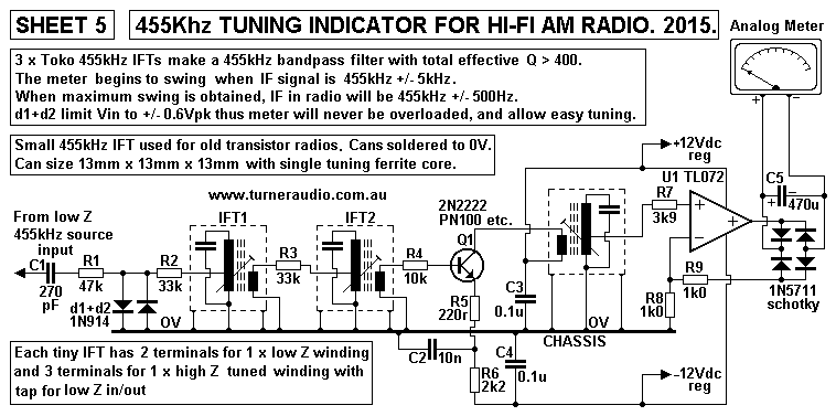
So I built a second additional IF amp with bjts and 3 x IFTs found in transistor radios to make a band pass filter
with band about 1.2kHz to power a tuning meter.

Sheet 5. Tuning indication.
Kitchen-AM-radio-schem5-455kHz-tuning-indicator-2015.GIF
If tuning indicators were ever used in old radios, a magic eye tube or a meter was powered by the -Vdc
AGC level. But for most old sets you just twiddled the tuning knob for the best sound with least HF sibilance.
There was only one peak of IF at 455kHz, and that was where audio volume was maximum. Domestic radios
were always tuned by ear for long distance or short wave when meters or other indicators didn't show any reaction.

For hi-fi AM radio, the IF pass band is flat so AGC hardly changes for IF change of +/- 6kHz.
The additional IF amp ( on a small board at rear of case ) has overall Q > 400 so that the meter only moves
from far left to right when IF is between about 447kHz and 462kHz. When I peak the meter with a tiny
movement of tuning knob I can get IF between 454.5kHz and 455.5kHz, ie, within +/- 500Hz of wanted F.

Googling anything like this drew a blank; nobody else seems to gone to the trouble I have, and it appears
I have invented this indicator circuit method. There are schematics using 455kHz ceramic filters or crystals but
nothing was able to do what I have here, with a high enough Q and simple circuit above.

The 3 tiny IFTs used in old AM radios are still easily available. Unlike IFTs for tube radios, these have only
one tuned primary winding with a tap at 33% and a fixed C across all turns. Idc feeds the tap from +12Vdc,
and bottom of coil is driven by collector. There is a second winding with no C and less turns than tuned winding.
So there are 6 connections, 5 for the coils and 1 to ground the transformer can. The secondary coil with less
 turns suits the low base input resistance of a following stage. All this must be well understood before working
with such junk.

With such IFTs, there is no flat topped pass band to widen the AF response. I am exploiting the limited
bandwidth to make an indicator. The high Q of these LC depends on not having R or a bjt loading all primary turns.
Most cheap transistor radios and AM sections of AM-FM tuners achieved IF pass band of 3kHz, allowing only
1.5kHz of audio bandwidth, so Q of 2 IFTs is about 150. With 3, Q is over 400.

The 455kHz signal from low resistance source at V4 cathode has bandwidth = 17kHz, so it does not affect the
Q of the bandpass filter for meter.

Brighter tech heads reading here may laugh at what I am doing and insist I should use a phase locked loop
with 455kHz crystal controlled oscillator to provide a +/- Vdc signal to drive a meter or magic eye.
I won't hold my breath waiting for them to post up a suitable simple schematic which they have tried and tested.

Or they may like me to use a 455kHz crystal controlled oscillator with PLL and apply +/- Vdc to alter bias of
vari-cap diodes to change the C of the tuned oscillator LC network. This means once a station is tuned, there is
Automatic Frequency Control, AFC, which locks the variable oscillator F to whatever F is required to give a
455kHz difference between station RF and the oscillator RF. If the station is at 846kHz, oscillator should be
at 1,301kHz. The PLL should try to keep the oscillator at 1,301kHz if the RF of input LC set is tuned away
up to +/- 10kHz from 846kHz. Once tuned far enough away from 846, say to 864kHz, there is insufficient IF
signal generated to be compared to crystal 455kHz oscillator, so the "lock" releases to let the variable tuned to
vary when tuning for another station. This way a set is either tuned, or it isn't, but the RF still needs to be tuned
to give maximum RF input to the mixer tube so a meter driven by AVC Vdc is needed. There can be LF oscillations
if the PLL "hunts for a lock".

Ordinary varicap diodes cannot operate in a tubed oscillator which generates such high signal the diodes conduct.
However, medium voltage zener diodes of say 68V, 5W rated can have up to 50Vdc applied and they don't
conduct, so being better for tubes than low voltage rated varicap diodes. I have used 5 in parallel to make a
splendid vari-cap to change an RF gene for 455kHz to give FM, 455kHz +/- 40kHz, to plot response of the IF
amps, similar to using a "sweep", or "wobbulator".

If anyone wants to go to all this trouble, they are welcome. An AM radio can easily have far more complexity
than it really needs to have, and if you want to explore complexity for better performance then I suggest
synchronous reception and AF detection.

I welcome anyone to give me a SIMPLER schematic involving a crystal controlled 455kHz oscillator and a
ratio detector or IC to compare radio IF to the oscillator F and thus be able to produce a similar
easy-to-built-and-use outcome. Ratio detectors with 6AU6 in FM tube radios became very popular but needed
a special 10.7MHz IFT. Those are fairly easy to make with solid wire, but for the AM band it may be more difficult.

Much more about AM radio may be read in books written before 1960. RDH4 is quite good. I hope my
approach with tubes performs better than anything from old books which seem to show the same basic stuff full
of shortcomings so carefully included by penny pinching company accountants.

I cannot advise anyone to make their own IFT transformers. They are most unlikely to get the performance
available from the many old and usable IFTs from the past which used litz wire and just the right type of ferrite
cores with screw adjustment and the right size of shielding can.

The larger cans about 100mm high and 40mm x 40mm seem to be best to get good skirt selectivity and Q.
The can size relates to coil size, and the coils used in old tubed radios had to be easily made by women working
at benches while chatting about recipes and their dim witted husbands. When IFTs were miniaturized to suit tiny
SS radios arriving from Japan in 1960, I guess automation replaced the highly skilled ladies, or the Japanese
girls all strained their eyes.

I have not tried use of 2MHz IFTs which would need an oscillator F from 2,531kHz to 3,701kHz.
Almost no maker I know ever made sets with IF = 2MHz, perhaps because there was a chance broadcast band
sets could interfere with other communications sets because of the high oscillator F. Maybe regulatory authorities
banned 2MHz. If the LC for 455kHz has Q = 45.5, then pass band = 10kHz but if the IF = 2MHz, the same Q of
45.5 gives pass band 39.9kHz, and audio BW of 20kHz, somewhat excessive for AM. In practice, such higher
Q as F rises may be unlikely and a lower Q gives pass band is too wide. So you'd need 3 IFTs. There are a
couple of old schematics online, one by Miller, but I've not had time to try them.

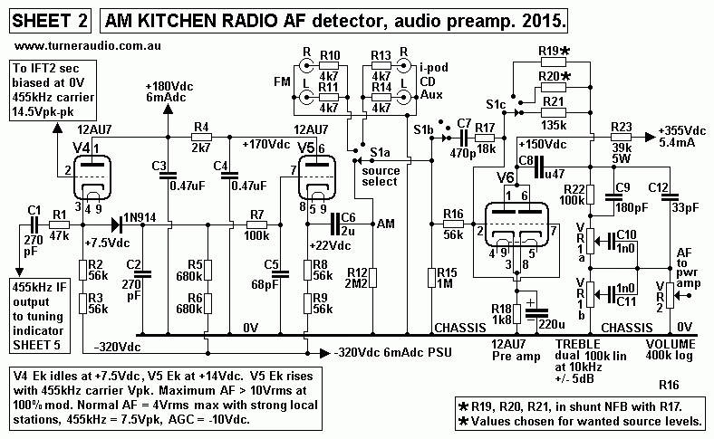
SHEET 2. AM detector Sheet 2.
Kitchen-AM-radio-schem2-AFdet+line-preA-2015.GIF
This arrangement of triodes cannot be found in any AM radio sold by any radio manufacturers before today.
The IF signal from IFT2 secondary is a fairly high Z source, and feeds very high Z input to grid of V4, 1/2 12AU7.
V4 is in cathode follower mode and its input C < 20pF so it has little loading effect on IFT2 LC.

V4 cathode has low Rout = 1/Gm = 1/0.0017 = 588r, and powers the 1N914 diode to charge C2 with half cycles
of 455kHz IF waves. C2 value is chosen to have reactance Xc of more than 2 x Rout at the carrier F.
Carrier F = 455kHz, and with C2 = 270pF, Xc = 1,294r. C could be less, but R value becomes too high and
the circuit becomes prone to noise. If C is higher, the peak charging current in 12AU7 may become too high and
cause grid current which limits the IF input signal.

AF DETECTION WITH DIODE, CAPACITOR & RESISTOR.
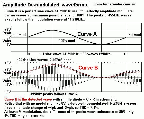
Fig 2. Basic Waves.
AM-waves-455kHz+14kHz-de-modded-2015.GIF
Curve A shows a 14kHz AF wave used to amplitude modulate a 455kHz carrier wave seen Curve B.

Amplitude of peaks of 455kHz follow same shape as the applied AF signal assuming the de-modulation
process is linear. The amount of modulation shown is the maximum possible, ie, 100%. The AM wave shown
may be detected with diodes + C + R to give two opposite phases of the modulation signal.

If AF is increased beyond what is needed for 100% mod, the "envelope shape" begins to have asymmetric
clipping on one side of the modulation wave. The clipping is detected and recovered audio modulation has
rapid increase of THD.
 
Curve B is the possible IF wave after an IFT in a radio set. It is usually a high Z signal source which I think is
best converted to low Z with a cathode follower or darlington pair emitter follower.
The followers give lower THD than without them when driving a following passive diode+C+R network.

In practice, although some modulation from radio stations reaches 100%, most of the AF modulation is done
at an average level of 25%. This is easily confirmed when viewing output of a radio station at V4 cathode.
Radio stations often use audio compression to reduce dynamic range and have higher average mod levels
and therefore a "louder sound" But many locals here show most modulation is under 30%.
When using a test AM signal with 100% modulation with a single AF, say 400Hz, many receivers will have
less than 100% mod in their IF signal because of phase shifts in the mixing process before IFTs, so max
modulation depth at receiver detector may be 90%. Nothing is perfect, But this aspect is not a problem.

Fig 3. Detecting AM waves.
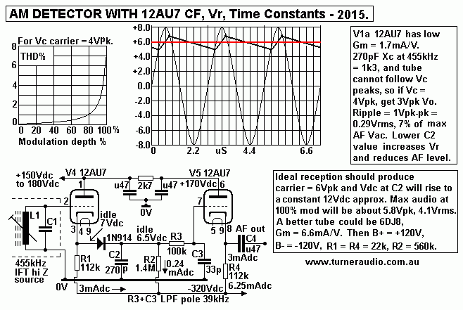
AM-detector-12AU7-CF-Vr-TCs-2015.GIF
Fig 3 explains the waves in my kitchen radio AF detector.
Without any 455kHz signal the Vdc at C2 = 6.5Vdc, about 0.5Vdc below cathode idle Vdc. Biasing of
V4a grid = 0Vdc, and about 3mAdc flows in V4 and V5. I show the 455kHz non modulated wave at V4a grid
as 8Vpk. From this, diode and tube turn on resistance produces Vdc at C2 which is +6Vdc above the idle Vdc
of +6.5Vdc. So with carrier shown, expect to see Vdc at C2 = +12.5Vdc. To view the AF waveform after C2,
best point for CRO connection s cathode of V5, a low Rout port, and 455kHz ripple will be very low after LPF
R3+C3. 
Without modulation you will see a flat line which I show in red here. The Vdc level should not change when
modulation between 0% and 100% is present.

The 455kHz ripple voltage should have fairly constant shape and amplitude with low frequency AF modulation
up to about 95%. This is due to C2 being discharged by R2 connected to -320Vdc rail. The C2 discharge
current remains a virtually constant 0.24mA. The forward voltage drop across diode is reduced because
it has idle current even where 455kHz swings towards 0.0Vac during 100% modulation. Thus distortion
caused by change of ripple voltage amplitude during detection is much reduced. This detector works better
than if you have R2 of much lower value connected to 0V instead of -320V.

I have chosen -Vdc rail = -320Vdc because it was so easy to do with a couple of power diodes and C from
a PT with a suitable HT winding. But -120Vdc would also be fine providing the R1, R2, R4 values are reduced
to give same idle Idc. The circuit works best where Vdc between top C2 and a Vdc rail is at least 10 x
expected maximum carrier Vpk.

I show V4 and V5 = my favored 1/2 12AU7 but other triodes could be used, 6DJ8, 12AT7, 6CG7, 6SN7,
or trioded 6BA6, 6AU6. Never use 12AX7, 12AY7 which have such low gm they fail to work properly at all.
J-fets could be used but these cannot produce such a high output audio level and Vdc rails must not exceed
+/- 24Vdc.
The humble 12AU7 can make up to 25Vrms as shown, so overload distortion is not a worry.
A darlington pair follower with bjts can be made using 2N2222 + BF469 which should work very well with
+/- 50Vdc rails and slightly higher C2, 470pF and different R values suit.
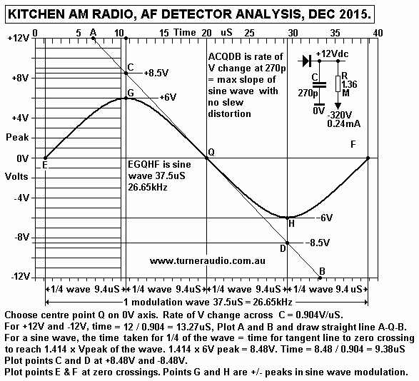
Fig 4. AF detector time constants
AM-detector-Kitchen4-radio-C&R-TCs-2015.GIF
Fig 4 shows an audio sine wave = 26.65kHz, with a wave time = 37.5uS, and with amplitude of 6Vpk, 4.2Vrms.

The C = 270pF, and R = 1.36M. There is an idle Idc flow = 332V / 1,360k = 0.244mAdc.

The time constant for C and R is calculated :-
Time in uS = CpF x R ohms / 1,000,000 = 270 x 1,360,000 / 1,000,000 = 367uS.

This means that if current input to diode is switched off, the Vdc would fall by 0.63 x Vdc across R, so
from 332V to 122.8Vdc in 367uS, and then to 45.4Vdc after 734uS and so on until the V across R = 0V.

The initial current I in R = 0.244mA, but it declines as V across 1.36M reduces so the rate of discharge
from C slows so the complete discharge of C takes a long time.

But if could keep the discharge current from C constant, we would find the time taken to V across R to equal
0V is equal to the time constant.

If the voltage change across R is a small fraction of the total possible V change, then the rate of V change is
very nearly constant and we can draw the line of this as a straight line on a graph. It makes the investigation of
the behavior of our circuit much easier to draw, and contemplate.

The rate of V change across C determines the maximum audio level and the highest audio frequency without
slew distortion.

For a small fall in voltage of say 6Vpk, the current is virtually constant so rate of V change is calculated :-
Rate of V change = max Vdc / TC = 332V = 367uS =  0.904V/uS.

Now the time between peaks of carrier 455kHz = 2.2uS, therefore Vpk-pk fall in Vripple = carrier
wave time x rate of change = 2.2 x 0.904 = 1.988V.
So say 2Vpk-pk, and for a saw tooth wave it is 0.57Vrms = 13.6% of the audio voltage = 4.2Vrms.

If the AF level is doubled to 8.4Vrms, then ripple voltage remains the same and is 6.8% of AF.
The fastest rate of V change at zero crossing with 26.65kHz doubles, so there will be slew distortion.
Therefore the fastest sine wave modulation can be 13.33kHz.

The analysis here tells us we can get good audio HF performance while keeping Ripple voltage low,
while not overloading the 12AU7 and causing grid current flow. If C is increased, overloading could occur,
and grid current could affect the input wave and load the IF circuit. If C is reduced Vripple increases,
recovered Vm reduces, and R noise increases.

In practice, if the modulation below 5kHz is 4.2Vrms maximum the R could be 2M7 to discharge C 270pF.
The detector would pass 13kHz with no slew distortion for 4.2Vrms. However all audio speech and music
signals have most of the energy between 80Hz and 1kHz, and above 5kHz the the signal voltage falls at
about 6dB/octave so there is little need for the detector to ever have to cope with more than 1.4Vrms at
13kHz so there is no slew distortion. The higher R value halves the ripple voltage.

Other detectors may use a class B SS amp as I show at AM modulation.

Those SS fetishists can dive much deeper into AM as described at
http://www.epanorama.net/sff/Radio/Receivers/Synchronous%20AM%20Radio%20Detector.pdf

While some radios use the -Vdc after detector, I found it better to generate -Vdc for AVC using a diode
and low value C fed off IF amp anode and equal to what I show in SHEET 1 above with IN914.

V4 cathode is directly coupled to V5 grid via 1N914, and R7 100k. I have C5 68pF to 0V so that
output from C2 has low pass filter with -3dB cut off at 23kHz. This means virtually no attenuation occurs
to audio up to 9kHz, the maximum we need to worry about for AM radios.

But attenuation for 455kHz is from 0.55V ripple to 0.03Vrms which cannot affect V6 preamp or following
power amp stages.

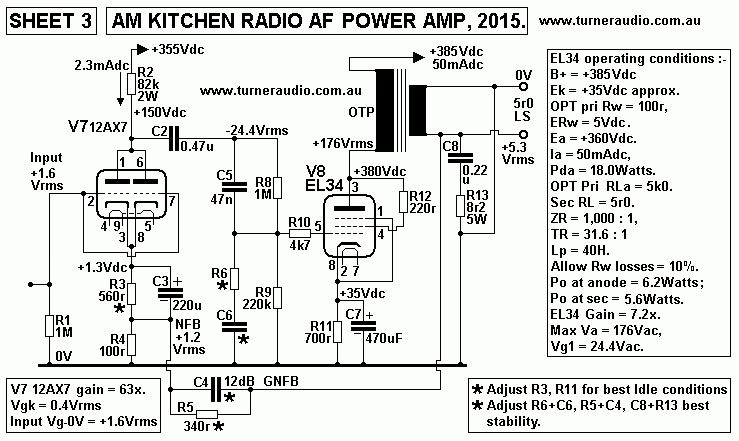
SHEET 3. Kitchen AM radio Sheet 3.
Kitchen-AM-radio-schem3-AF-pwramp-PSU-2015.GIF
The AM radio power amp uses paralleled 12AX7 input tube driving EL34 in triode mode. This amp is state
of the art SET amp, with the usual features to get true hi-fi performance.
The EL34 triode idles with Pda + Pdg2 = 17.5 Watts, well short of maximum Pda rating = 28W. The EL34
will last a very long time if idle Pda = 0.63 x max Pda rating. Other output tubes strapped in triode could be
KT66, 6L6GC, 5881, 6550, KT88, KT90. Adjust R11 cathode resistor so idle Pda < 0.63 x rated max Pda.

Least THD would be with KT88 in triode where idle Pda = 26.4W, Po max for 5k0 anode load = 5.5W at
4% THD, if Ea = +350V, grid bias = -39V, Iadc = 75mA, or you have B+ = +390V, Ek = +39V,
R11 = 520r. Load for max Po with KT88 = 2k9, and Po max = 7.9Watts at 7%, Normal loud listening levels
with 5k0 load will rarely exceed average of 1W when THD = 1.7%. There is some 2H cancellation between input
driver V7 12AX7 and output tube. If GNFB is 12dB then THD > 0.5% at 5.5W for 5k0 load.
EL34 will give similar THD figures for same 12dB GNFB at 4.5W with 5k0 load.
Notice the R&C networks for HF and LF stability. High quality 8W rated OPTs for 5k0 : 4r ,8r, 16r should be
used for 6550/KT88. But for EL34 triode my OPT is 6W rated and was formerly used with EL84 in SE pentode
mode in a non-repairable 1965 tape recorder where OPT was slightly better than those used in old radios.

You should find the sound quality is just magical.

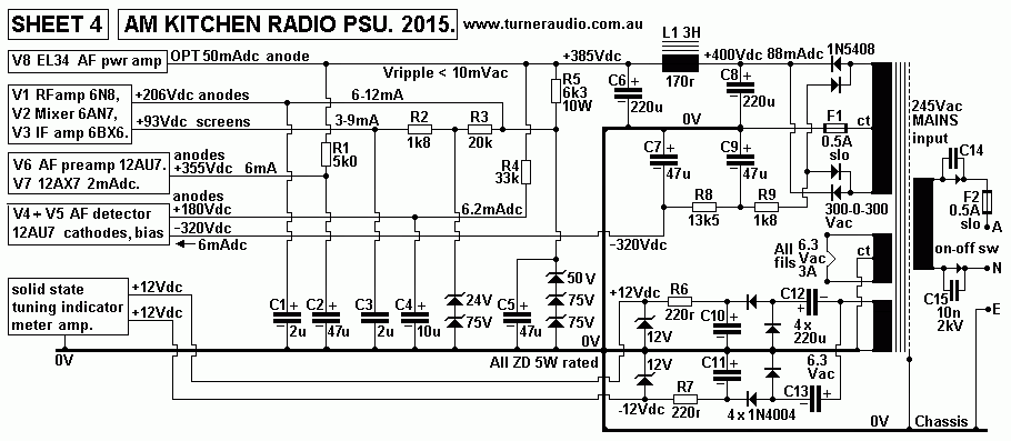
SHEET 4. Kitchen radio SHEET 4, PSU.
Kitchen-AM-radio-schem4-PSU-2015.GIF
This PSU provides :-
B+ = +385V at 88mAdc with CLC filter to feed all anode supplies.
B- = -320V at 6mAdc for cathode load resistance current.
6.3Vac with CT for all heater filaments.
+/- 12Vdc for the solid state 455kHz frequency detector for tuning meter.
-------------------------------------------------------------------------------------------
I repaired a large number of tubed and some solid state AM - FM radios over 19 years between 1993 and 2012
when I retired. Not one equals or betters the performance I get with above schematics. I did re-engineer a
number of large floor stander sets plus a few "mantelpiece" sets and obtained a wealth of experience of how
to get old junk to sound far better than when they sold to the public 60 years ago. Back then the public rarely
heard any hi-fi anywhere, so their expectations were very easy to satisfy.
-------------------------------------------------------------------------------------------
Canberra's AM radio stations.
666 5kW ABC Canberra(2CN) - Canberra ACT news/talk
846 10kW ABC Radio National (2FM) - Canberra ACT
1008 300W Sky Racing Network (2KY) - Canberra ACT sports/racing 
1053 5kW Forever Classic (2CA) - Canberra ACT classic hits 
1125 2kW RPH Print Radio (1RPH) - Canberra ACT reading service 
1206 5kW Talking Canberra (2CC) - Michell ACT news/talk 
1440 2kW SBS Radio 2 (1SBS)|rep - Canberra ACT public/multi-langua service
1629 - Rete Italia|rep - Tuggeranong ACT Italian 
1638 - Rete Italia|rep - Canberra ACT Italian 
1647 400W 2ME Radio Arabic (1ME)|rep - Canberra ACT community,cl. hits,pop,narrowcast Arabic

Canberra's FM radio stations.
87.6 5W Raw FM|rep - Canberra ACT dance/urban
87.8 1W UCFM - Canberra ACT college (Univ.-Canberra) 
88.0 1W Radio Austral|rep - Canberra ACT community espanol 
88.7 100W ACT TAB (1TAB) - Tuggeranong ACT sports (racing) 
89.5 100W Valley FM (1VFM) - Tuggeranong ACT community 
90.3 100W ArtSound FM (1ART/T)|rep - Tuggeranong ACT community/jazz/blues/world... 
91.1 20kW CMS Radio (1CMS) - Canberra ACT community multi-languages 
91.9 20kW One Way FM (1WAY) - Canberra ACT religious 
92.7 20kW ArtSound FM (1ART) - Canberra ACT community/jazz/blues/world... 
94.3 100W One Way FM (1WAY/T)|rep - Tuggeranong ACT religious 
96.7 500W QBN-FM (2QBN) - Queanbeyan NSW community 
97.5 300W Hot Country Canberra - Queanbeyan NSW country,narrowcast 
98.3 20kW 2XX FM (1XXR) - Canberra ACT community 
99.9 100W ABC News Radio (2PB/T)|rep - Tuggeranong ACT news
100.7 200W 104.7FM (2ROC/T)|rep - Tuggeranong ACT CHR-pop 
101.5 80kW ABC Triple J (2JJJ/T)|rep - Canberra ACT
102.3 20kW Mix 102.3 (1CBR) - Canberra ACT hot ac 
103.9 80kW ABC News Radio (2PB/T)|rep - Canberra ACT news
104.7 20kW 104.7FM (2ROC) - Canberra ACT CHR-pop 
105.5 80kW SBS Radio 1 (2SBSFM)|rep - Canberra ACT public/multi-langua service
106.3 80kW 1ABCFM - Canberra ACT classical 
107.1 100W Mix 102.3 (1CBR/T)|rep - Tuggeranong ACT hot ac

Canberra's digital radio stations.
10B    104.7FM - Canberra ACT CHR-pop 
     ABC Canberra (AM666) news/talk 
     ABC Jazz jazz 
     ABC Radio Grandstand sports 
     ABC Radio National
     Chemist Warehouse Remix hot ac
     Double J alternative 
     Forever Classic (2CA,10523AM) classic hits 
     Hot Country Canberra (97.5FM) country,narrowcast 
     Mix 102.3 hot ac 
     Mix '80s CHR-80s
     Mix '90s CHR-90s
     My Canberra Digital hot ac
     SBS Chill electronic,chillout
     SBS Pop Asia pop-Asian
     SBS Radio 1 (105.5FM) public/multi-langua service
     SBS Radio 2 (1440AM) public/multi-langua service
     Talking Canberra (2CC,1206AM) news/talk 
     The Edge Digital CHR-rhythmic 

  Triple J Unearthed local/unsigned artists
 

To Index page

To radio re-engineering
-----------------------------------------------------------------------------
Additional general notes.

AM radio broadcasts in Australia are officially from 531kHz to 1,602kHz. Some stations are allowed to
operate conditionally to 1701kHz. The RF carrier of each station is controlled by a crystal or equivalent and is
at a frequency exactly divisible by 9.0, ie, all AM stations at on 9.000kHz spacing across the band, 531,
540, 549 etc. Audio modulation frequencies are allowed up to 9kHz with rapid attenuation above.

Canberra's ABC Radio National has carrier = 846kHz. The RF amplitude determines the volume of the
sound heard, while the rate of change of amplitude determines the frequencies heard from audio between
20Hz and 9kHz. This is linear AM modulation. The 846kHz transmitted radio signal has a spectrum
of "modulation products" between 837kHz and 855kHz.
Amplitude modulation of an RF signal 'F1' by a second audio signal 'F2' produces a radio signal with a
fixed F1 signal, and "modulation products" above and below F1, = (F1 + F2) and (F1 - F2). If carrier
= 846kHz and modulation = 5kHz, 3 RF signals are present, the 846kHz carrier plus modulation products
at 841kHz, and 851kHz. The "products" are called lower and upper sidebands. The carrier is at constant
amplitude, with sidebands each able to vary between zero and 1/2 the carrier amplitude for modulation
levels between 0% and 100%.

An oscilloscope will show the AM wave as a single F sine wave at 846kHz but its amplitude is varied
at a rate of 5kHz. There are really 3 frequencies interacting, and a spectrum analyzer with very narrow
band filters will show the single 846kz carrier and two sideband peaks each side of carrier, 841kHz
lower sideband and 851kHz upper sideband.

If the modulation process is not linear some additional sideband F are created. If the carrier Vc = constant
2Vrms, then each upper and lower sideband peak can rise to a maximum of 1Vrms. This is 100% modulation
depth. If more AF is applied to modulator, the envelope seen on the oscilloscope will have very rapidly
increasing THD, and the detected audio signal will appear to clipped on positive or negative wave peaks.
The oscilloscope shows that if carrier wave without modulation = 2Vrms, then the maximum envelope wave
voltages above and below 0V are each also 2Vrms.
Two audio wave signals of 2Vrms are able to be detected, each AF wave having opposite phase.
99% of all AM radios detect only one phase of audio, and often use a single diode plus C + R which works
the same as a 50Hz 1/2 wave power rectifier. Most radios generate a negative going audio wave, ie, the
lower 1/2 of the AM wave so that the -Vdc of carrier also detected can be used in sets for AGC.
All old tube radios had 1/2 wave detectors producing up to maybe -25Vdc and possibly 25pk volts of audio.
Full wave rectifiers and voltage doublers all were not needed, and were found to be difficult to optimize.
It is fairly easy to detect both phases of audio modulation to produced a balanced AF signal but not one
maker has ever seen any benefit because the single ended AF source was adequate, even when a PP audio
amp was used.

THD/IMD and poor audio bandwidth of old radios is due to several factors:-
1. Non linear IF amp distorts the envelope shape, adding several % THD to the AF detected.
2. Diode peak detector is not linear, adding several % THD....
3. Detected AF fed to cap coupled volume pot which causes cut off distortion which isn't understood by anyone,
but it happens.......
4. Audio amp has minimal stages, usually high ยต triode feeding 6V6 tetrode in tetrode mode but without any
GNFB, adding several % THD.
5. PSU is poorly filtered. You know the radio is turned on by the hum you hear.
6. Very poor speakers in the same box as radio, adding several % of THD/IMD at all levels above a whisper.
7. Noise pick up by RF input stage using small radio frequency transformer and 3 meter long wire antenna.
The 7 factors may produce harmonic artifacts which may exceed the wanted HF audio content which is excluded
by the sets poor AF bandwidth of say 3kHz. So the missing wanted HF is replaced by bad sounding sonic garbage.
 
Audio bandwidth less than 3kHz is determined by the overall RF and IF bandwidth of tuned LC networks
in the set being less than 6kHz. Most AM superhets have 5 tuned LC circuits, one RF LC, and 4 x IF LC.
The bandwidth of each LC may be 8kHz to allow 5kHz of audio. But when 5 x LC are cascaded, the overall
RF+IF BW can be 4kHz, allowing only 2kHz of audio BW. These  radios have good "skirt selectivity",
ie, a 5kW local station cannot be heard when tuned to a low power local station only 45kHz away; the
attenuation is over -60dB. The skirt selectivity is good for listening to distant stations, but I never need to
hear distant stations because my ABC favorites are networked so a distant ABC RN station has the same
program as the local RN. Many commercial and regional radio are stations are networked and give
boring pop music or torkbak with long adds so none are worth a listen.

Audio bandwidth is determined mainly by the receiver IF bandwidth.
Fig 5.
IFT-455kHz-LC-coupling-response-jan-2016.GIF
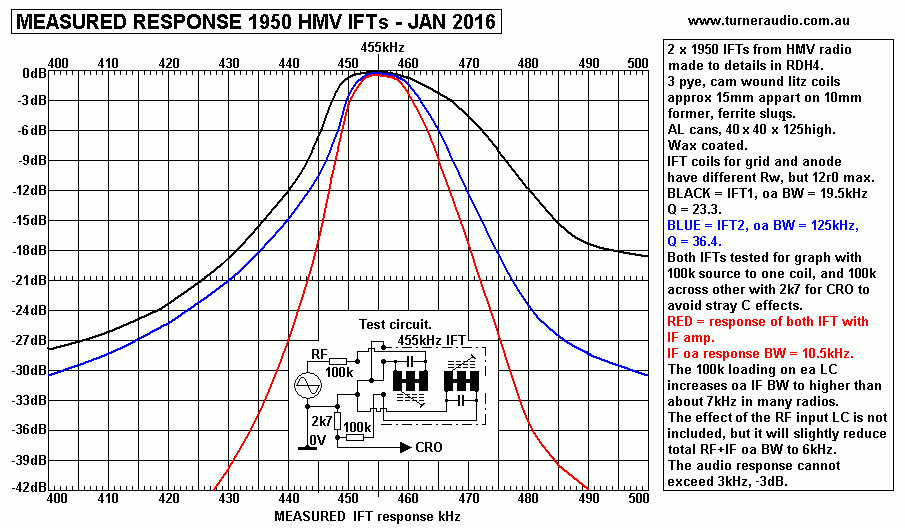
Fig 5 shows 2 measured responses for typical well made IFTs for HMV radios made in 1950s using litz
wire coils cam wound in 3 pyes. BLACK and BLUE curves are for IFT1 and IFT2, and their summed
response is shown as the RED curve. Notice the curves have asymmetrical shape above the center F = 455kHz.
This is due to slightly higher stray coupling between input test signal and output leads at higher F.

The curves show the coils of both IFT or at least one IFT could be moved closer for more IF BW if wider
AF is wanted. Notice the phasing of connections for primary and secondary coils. The response will measure
very poorly if the incorrect phasing is used, and the result with best attenuation away from 455kHz is the correct
connection. Many who making their own IFTs now will need to realize the importance of coil distance and
connection phasing. Some ppl will use fixed RF coils with L = 477uH, ( 0.47mH ) and C = 260pF using
220pF fixed and parallel to 10-50pF trim cap.

The overall RF and IF bandwidth is mainly determined by the two IFTs in most sets, each with two
magnetically coupled tuned LC. The Q of the litz wire coils produce a high Q over 40. The amount of
magnetic coupling of pri and sec IFT LC is determined by the distance between the pair of IFT coils, and
this determines pass band response shape.

Coils say 20mm apart, magnetic coupling is low, insertion loss is high, maybe -20dB but selectivity and Q
is high, which best suits long distance reception. with low AF bandwidth and low noise.
Coils say 15mm apart, magnetic coupling is medium, insertion loss -12dB, and selectivity slightly less but OK,
and Q is lower, permitting 4kHz audio bandwidth.
Coils say 12mm apart, magnetic coupling high, insertion loss -10dB, selectivity OK for local stations at least
45kHz apart, Q is low, and AF is widened to a maximum of about 9kHz.
Fig 5.
IFT-455kc-coupling-effect-BW-jan-2016.gif
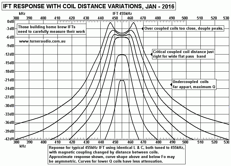
Fig 5 shows the response of a typical 455kHz IFT from 1950s. The AF bandwidth is always 1/2 the IF bandwidth.

This all assumes all the IF LC are tuned to 455kHz. However, when 2 tuned LC are brought close enough, the
IF pass bandwidth cannot be widened to more than maybe 16kHz before the shape of the pass band becomes
twin peaked. It becomes almost impossible to easily adjust the tuning of each LC to 455kHz unless one has a
signal gene with F meter plus a sweep or wobbulator or FM gene display the response of the IF so symmetrical
twin peaks are achieved.

The twin peaks of IFT1 can be both reduced if the pri and sec are tuned slightly above and below 455kHz.
This makes the pass band flatter hence flatter audio response.

There is often good reason to slightly reduce distance between any 2 LC in a given old IFT to be able to get
more IF BW and thus get wider AF BW. But to the inexperienced DIYer, the mod is difficult, can ruin the IFT,
and it needs experience, a good signal gene and F meter and a CRO + probe with 10:1 function.

Should anyone want to wind their own IFTs, I suggest the page at http://213.114.136.42/blocks/if-txfmr_tube_00.htm
------------------------------------------------------------------------------------------------------------
Synchronous reception.
For a good synchronous design you need an RF oscillator with its sine waves exactly synchronized with those
of a station to which you are tuned. Before solid state chips were invented, phase locked loop ( PLL )
techniques were rarely used; I have never seen a tubed PLL. So a "locked oscillator" was used so a small
sample of wanted station RF was amplified, then limited, then applied to an oscillator so that it "pulled" the
oscillator Fo to being the same as the wanted station. This is OK for FM radio where a constant level 19kHz
pilot tone can be used to lock a circuit producing 38kHz sub-carrier for stereo. But for AM, I found the locking
didn't want to work so well because if the modulation reached 100% the locking signal ceased so oscillator
would jump away from lock, and the better way would always be PLL with stand alone oscillator controlled by
Vdc applied to vari-cap diodes.
I did try once to make a "synchrodyne" set using a Mr D.G.Tucker's circuit from 1947. I needed special trifilar
RF transformers and 4 x Ge diodes for a ring diode mixer network. I found no available info about such
transformers in 1999, and I easily concluded the superhet was a whole lot easier.

In 2015, I investigated how a Gilbert Cell works, usually with bjts inside IC, as in MC1496.
I found it could be done with 3 twin triode 6DJ8/12AT7, but MC1496 has 6 bjts for the basic pair of cross
coupled differential amps. I found discrete bjts or triodes were all so fiddly and complex I gave up.

To produce an audio signal in a receiver which is equal to the audio used to modulate the the transmitted
carrier and without any interference from any other station, there are two basic requirements :-

1. The receiver must have RF pass band of twice the highest audio BW used for modulation measured at the
 input to the AF detector circuit. If the highest AF = 9kHz, ideally the RF pass band at AF detector input is
18kHz. Beyond this pass band, there must be a high rate of RF attenuation so a strong local local a station
45kHz away from the wanted station has a level at least -60dB below the wanted station.

2. Radio stations with the same carrier F as the wanted station must be located very far away so their signal
strength at receiver is so low it cannot be heard. From searching listed stations, I found one at Cairns on 846kHz,
same as a Canberra station. Distance is over 2,000kM. Local stations are not closer than 45kHz apart.

AFAIK, the highest audio F used for AM modulation in Australia is 9kHz, and without any emphasis of high
of low AF. But many stations use audio compression to make everything sound more lively. AM radio stations
across Australia are 9kHz apart, so when listening to distant stations, it may be possible two stations are 9, 18,
or 27kHz apart so that both are heard if the selectivity is poor. Where they are 9kHz apart, you can get a 9kHz
whistle because the carrier of one station 9kHz away from a wanted station is detected as a 9kHz tone.
The other side bands of the other station are also detected and cause "monkey chatter". For listening to distant
stations, or "DXing" a wider the RF and IF bandwidth in a receiver makes it less possible to just hear one station.
Older AM radios were often made with far less RF and IF bandwidth, perhaps only 4kHz, which allows only
2kHz of audio. While these may be OK for speech it will never be hi-fi. Having a directional antenna can
improve DX listening, but such things must be large, and interest in AM is now much less than in 1955.
Short wave reception also depends on good selectivity and low total IF and RF bandwidth.

Solid state receivers often have only 3 tuned circuits, one input ferrite rod plus 2 tunable IFTs with a single LC.
These have high Q, and allow about 2kHz of audio, but away from the tuned F the "skirt selectivity" is much
less than in tube sets with 5 LC with medium Q, The RF input LC and the 4 LC in the pair of IFTs, which
produce a flattened pass band.

If you want to tune to say 1,008kHz here, the SS radio will appear at first to be able receive it OK but
the AF BW is often only 1.5kHz. Attenuation of an unwanted station say 45kHz away 1008 may only
be 12dB with one tuned LC even if it has a high Q. 90kHz away from 1008 may be give 18dB, so
that 3 tuned LC give 54dB, not so good if the unwanted station has signal strength 20dB higher than
wanted. But with 5 LC of a typical tube radio, 60dB attenuation is achieved easily at 45kHz away from
wanted.

Before about 1930, many AM radios were "TRF" types using at least 3 simple RF triode amps with LC
 in series, each with a separate tuning knob. All 3 knobs had to be each adjusted to get a single station,
and no doubt many domestic arguments were caused by those unable to handle the radio set properly.
Each tuning knob pointed to a numbered dial so people would write down a list of numbers for each
station, so to tune a radio was like having to know the numbers of a lock on a safe, or a six digit telephone
number. Oh what fun.
Some TRF sets had a 4 gang tuning capacitor so four LC could be tuned with one knob without 4
confusing interactive knobs. The multi gang cap was installed in the very expensive sets for the rich,
but audio bandwidth was always poor. Each LC had to be very carefully set up to ensure the tuned F
of each was the same regardless of the knob position. If the Q for each was 50, then at 1,008 kHz the
RF BW = 20.16kHz, allowing 10kHz of AF BW. But with 4 LC, the effective Q increases to 142
allowing 3.5kHz of AF. At 45kHz away from 1008kHz, attenuation is about -48dB, and less than
the usual better -60dB or more with 5 LC in a superhet.
 
Development of the "super heterodyne" type of radio in 1920s also meant only one tuning knob was
needed. The "superhet" could have 5 to 7 tuned LC networks with only 2 or 3 requiring tuning by
means of a two or three gang variable capacitor. (One of these tuning gangs was always for a tuned
local oscillator.) Some communications radios had a 4 gang cap to tune 3 RF LC at radio input with 1
gang for oscillator but they may have had been 6 to 10 fixed F LC for between 3 and 5 IFTs.

For 50 years after invention of the simple TRF AM radio, many claimed the TRF offered the best hi-fi
because less mucking about was done to  the RF signal before detecting the AF. A few ppl claimed a
crystal set tuner with no active RF amp was best. Well, now we have a crowded AM band with many
stations and lots of noise so beliefs about TRFs & crystal sets can safely be ignored. By about 1935,
nearly all AM radios were superhets, easily giving the one wanted station without another in the background.
Simple sets allowed serious short wave reception with a good antenna, and in 1935 you may have
listened to Hitler ranting and raving, marginally less tolerable than the Voice of America, specialist stations
guided by religion, socialism could be heard, plus a plethora of loud buzz sounds which were radio jammers
to drown out the "opposition"

For strong local stations the minimum superhet needs a single tunable RF input LC and four LC in two
IFTs, so 5 LC in total, and with the pass band having a flat topped profile 18kHz wide, -3dB.

The tubed superhet has at least a 2 gang tuning cap usually with identical gangs giving C range 5pF to 480pF,
typical. There is usually a 4-40pF trim C across each gang to get wanted range of RF and oscillator F.
A 10 fold change from say 480pF to 48pF gives a theoretical Fo change from say 531kHz and 1,701kHz
from RF radio stations. The 3.2 ratio is close to the square root of C change.
The oscillator F range is from say 986kHz to 2,156kHz, 2.18 ratio, with IF = 455kHz. To obtain this,
a cap of about 440pF is in series with the tuning gang fixed plates. This gives maybe 230pF to 48pF,
4.79:1 ratio, and F ratio is sq.rt. 4.79 = 2.18.

The difference between the RF and oscillator F is the IF = 455kHz in most sets. Some older sets have
lower IF, and some older communications receivers may have IF at 100kHz to exploit the higher Q
available with lower IF, and thus narrow the overall pass band and exclude noise when tuned to a low
power station.

Typical "mixer tubes" aka frequency converters are 6AN7 hexodes or 6BE6 heptodes. These have enough
electrodes for operation as a triode RF oscillator which feeds its output to an available input grid sandwiched
between screen grids so that effectively the tube acts as a non linear amplifier with TWO input ports.
These special tubes are designed to prevent much varying levels of RF signals from altering the oscillator tuning F,
and vice versa, and ensure operation without production of parasitic F. Their range of F can be from audio
signals to 50MHz. 
The oscillator signal in a mixer tube is a much higher signal than RF input signal. So the mixer anode current is
switched on and off at oscillator F rate. RF input between microvolts and volts produces intermodulation product
F which are osc Fo + RF, and osc Fo - RF.
The output anode current is fed to an IF transformer which is tuned to the IF, ie, say 455kHz. The oscillator is
set up to always be 455kHz above the tuned LC of the RF input circuit. If the RF input signal = 846kHz, and
oscillator Fo = 1,301kHz, then the difference in F = 455kHz. The mixer tube produces a large oscillator voltage
signal at IFT input, and when looking with oscilloscope one cannot see the wanted IF. But the IF is there, at a low
level, and IF LC resonance means that ALL F except 455kHz are excluded by L or shunted by the C.
If the IFT secondary LC signal is examined, we find far less oscillator Fo and presence of IF is seen easily.
The following IF amplifier pentode, say 6BA6 raises the low IF signal to apply to a second IFT with two LC and
the output has virtually no other signal present except the IF. And the IF signal modulation envelope looks exactly
like the RF input signal envelope, ie, the audio information has been transferred to a new carrier F, ie, the IF.
This process of "mixing" is more accurately known as frequency conversion and it was called "super heterodyne"
reception.

IFTs were typically wound with litz wire to make coils about 0.48mH. This L was bypassed with a silver mica 250pF
capacitor. The F is varied by adjust screws to change a ferrite slug position inside the coil former tube.
Many older pre-WW2 IFTs had variable capacitors, and used solid wire, not litz wire, and IF was lower, 220kHz.
IFT plus a an Al shield could be 125mm high and 70mm dia. The late 1950s IFTs used fixed C and variable ferrite
slug tuning and were typically 75mm high and Al cans 22mm x 22mm plan size. These later IFTs with litz wire produced
the highest Q and the two LC could be arranged for a fairly flat topped pass band with good "skirt selectivity" so that only
2 IFTs were needed in most AM receivers. The thousands of ladies working in electronics factories were required to
make items which gradually became smaller and more difficult.

Most typical early 1950 IFTs had primary and secondary litz wire coils wound on a common phenolic former tube
about 10mm oa dia and 100mm long fitted inside an aluminium can 110mm high x 50mm dia, or square section
40mm x 40mm, with coils about 15mm apart. These gave good Q, and I've found them to be the easiest to change the
distance between the two LC to slightly widen the pass band width.

Some older communication receivers had 3 IFTs, with an RF stage ahead of the mixer. Helicrafter had a knob to
turn a shaft to change IFT coil distance on 3 IFTs to dramatically reduce the IF pass band to maybe less than
1kHz which is better to detect a weak Morse code signal among other strong short wave stations and noise.
There was an RF input pentode and 2 IF amp pentodes, and having enough gain was not a problem.
Alignment was easy. With IF coils closest, The AF pass band was about 4kHz, enough to suit communication
speech and amateur radio operators liked these sets.

RDH4 offers a solution to increase IF bandwidth by switching in a few turns of a tertiary IFT winding to
increase primary and secondary coupling to give a slightly twin peaked response. See page 455, RDH4,
1955 Ed.
Trio and Kenwood and early Quad AM receivers had this feature. First you tuned in narrow band mode
for highest IF signal at a meter or "magic eye". Then you switched to "hi-fi" to add in the tertiary and audio
bandwidth could be increased magically from say 4kHz to 8kHz. But you needed to repeat this for each station
which is torture for radio surfers changing stations 20 times a night. Quad had The Best way of doing it.

I used recycled IFTs from 1950s with both IFT coils closer together and no switched tertiary. Because I have
good test gear, I was able to tune each LC in IFT1 to 450kHz and 460kHz, and thus get wide flat IF
bandwidth with both LC in IFT2 tuned to 455kHz.
To be able to tune the set properly I have a tuning meter powered by second IF amp with 3 tiny IFTs from
a transistor radio for a high Q and meter tell me when IF is +/- 500Hz away from 455kHz. The sound is
then better than all other AM sets I've owned, or repaired, and better than FM where the signal is from
the same networked source for AM and FM, as it is with news on ABC Classic FM and AM Radio National.

Keep soldering, and don't electrocute yourself.

Back to Index Page