SOLID
STATE AMPLIFIERS 2, BJTS.
This page slightly updated 2014, and includes....
Fig1. Schematic for one channel of 300W SS power amp with high
current bjt output stage.
MJL21194 and MJL21193 power device choice, thd in driver stage,
buffer stage cure, cross
conduction phenomena at 27kHz.
Fig 1A. Amp schematic re-drawn in 2014.
Fig 2. Schematic for 600VA psu for 2 x 300w amp channels with
choke input filters.
notes on psu, chokes.
Fig 3. Schematic of input switching, gain pots, input signal
limiting, bridging phase.
Fig 4. Schematic for detector of DC offset in output, speaker
protection.
Fig 5. schematic for metering.
Comments on metering. Why I won't repair any more Phase Linear 700
amps.
--------------------------------------------------------------------------------------------------------
300W BJT AMP FOR HIGH CURRENT INTO LOW LOADS.
A guy asked me to rebuild his Phase Linear 700 amps. These may
have been famous for being
"flame linear", and "failing with smoke" when the party got really
hot.
I made the case larger, increased the fins on the heatsinks to
what they should have been originally,
and used the following schematics below.
I apologize about the hand drawn and scanned schematics, but I
doubt there is great need for me
to spend 2 days redrawing Figs 1, 2, 3 , 4, 5 in MS paint for
everyone to enjoy better.
I doubt anyone would want to build the schematic shown.
Fig 1.
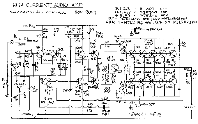
What a messy schematic!!
Fig 1A. This is better !!
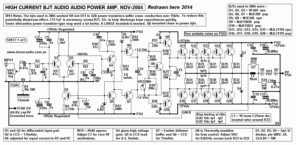
I don't want to waste too much time telling everyone exactly what
the finer points of this amp are.
It sounded OK at completion after 3 long weeks of hard slog. My
mental conclusion after the work
was "NEVER AGAIN !!" I just don't like power transistors in output
stages.
The 6 x MJL21194 and 6 x MJL21193 power transistors were chosen
because they were cheap,
available, have high voltage and current ratings and have been
used now in many high powered amplifiers.
They are flat pack types needing only one bolt to a heatsink. I
started off with the supposedly
wonderful output stage with as shown on the schematic and thought
that the darlington pair
arrangement wouldn't be too hard to drive with the MJE340/350 Q4,5
gain pair. But the output stage
Q9, Q10 base input resistance was still quite low and the NPN and
PNP output devices have such
a huge variation in hfe for each half positive and negative wave
cycle that thd was about 40% at the
driver stage so when a lot of global NFB was added I did not get
the low distortion measurements
which are so routinely easy and probably necessary with solid
state.
This is because the MJE340/350 Q4/5 pair have high collector
output resistance and the darlington output
stage base Q9/10 input resistance is low by comparison to the
collector resistance of Q4&Q5 driver stage.
I thought perhaps an arrangement as used in Crown amps with a
darlington triple output stage could be
used, but I don't like copying other designers. So I added
the buffer emitter follower Q6 with dc supply
from CCS Q7. The low Z output resistance of Q6 drives the base
inputs to Q9&Q10. Q8 is the VBE
transistor on the heatsink to control bias current in the output
stage.
The buffer reduced the effect of the low output stage input
resistance and the open loop distortion dropped
about 30dB and all was well. I was able to measure less than 0.01%
at near full power with the thd
reducing linearly with reducing output voltage right down to very
low power, and at a few watts I couldn't
easily measure the thd. There was no sign of any crossover
distortion.
However, a bad problem I encountered was with cross conduction
when testing at highish power at
27kHz. The output transistors appeared to be so sluggish about
turning off that the devices on each
ide of the PP circuit tended to stay on and seemingly ignoring the
directions of the driver amp.
This phenomenon leads to considerable current flow from rail to
rail through the output the transistors
and not all going through the load. What a horror! I finally
settled for the above schematic which seemed
to work fairly well to reduce the very poor behavior of cross
conduction. Even without a load connected
at 27kHz, the amp drew 10amps from each rail at Vout high
levels!!!! Mosfets never display this sort of
poor operation, and they don't need to be set up as darlington
pairs and they don't need a buffer stage.
Douglas Self mentions this phenomena at his website and gives only
limited advice about how to avoid
cross conduction. If there is/was a solid state guru, it might be
Douglas. I wondered how disastrous it
could be if cross conduction occurred at lower F, but even his
pages are largely free of
"what to damn well do when smoke threatens." Anyway, there was
little trouble at under 20kHz, and
the amp has not given trouble after many years and effortlessly
drove a 15" subwoofer and a
recording of a Space Shuttle launch had me think the window glass
might break, walls would shatter
and the roof tiles could fly away, but the amp soldiered onwards
without any smoke.
Although it sounded fair with wide range music, tubes and mosfets
are better.
The amp serves its owner well as a sub-woofer amplifier where it
can easily churn out 300W in bridged
mode into 8r0 and a lot more right down to 2r0.
Power output with +/- 55V rails and without allowing for slight
rail sag for sine wave
testing due to high PT winding resistance and some choke
resistance in power supply:-
8r0, 180W per channel,
4r0, 360W per channel,
2r0, 600W per channel.
Bridged :-
8r0, 360W
4r0, 600W.
Fig 2.
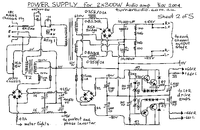
The power supply for the "Turner Linear" bjt amp used the original
Phase Linear power transformer.
Unfortunately, the tranny hummed badly like many PA amps do and I
didn't want to use the 62V
windings to make +/-86 volt rails because the possible 400W of
power into 8 ohms from such high
rails and from both channels wasn't wanted or needed, and may not
have been reliable. I built two
carefully designed swinging chokes which are 0.35Henrys on 32mm
stack x 25mm tongue GOSS
cores. These were varnished and potted in mild steel boxes with
roof pitch. This made two cubic
boxes with about 90mm along each side. The the original
10,000 uF caps and power transformer
were retained with the bridge rectifier. Noise with the choke
input set up was much less than with
a cap input supply since there are not such huge switching
currents to excite motion in the transformer.
I added rectifiers from the 62V-0-62V CT windings to directly
charge up a CRC filtered input amp
rails for the driver amp and added simple emitter follower
regulators and the final technical performance
was quite pleasing. There is some sag in the rails when continuous
power is used, but with rock
and roll taken up to occasional clipping the rails don't sag much.
There were no bad resonance
effects due to the chokes and 10,000 uF being series resonant at
about 3Hz.
For anyone trying to build an amp like this :-
You DON'T need to use choke filtering for +/- 57Vdc amp rails. I
only used LC because the rail
voltages would have been too high for this project. Anyone
building the 2 channel amp would
simply use a 1K2 VA power transformer with windings as follows :-
Primary = To suit the range of national mains voltages 250V, 240V,
230V, 220V, 110V, 115V, 120V,
and suit a frequency of 50Hz, with Bac max of 1.0 Tesla, to keep
noise and heat low.
Secondaries for +/- 57Vdc = Two windings of 43Vac x 20A rated.
Best practice is to make TWO MONOBLOC amps, and have a 600VA PT in
each with same
two 43Vac secondaries rated for 10Amps. These are most easily used
to make a center tapped
winding using ONE 35A rated bridge.
To make the +/- 57Vdc, the diode bridge will directly charge the
rail caps shown on Fig 1A as
30,000 uF, which would in fact be 3 paralleled 10,000uF rated for
63Vdc.
With 2r0 load on each channel at at full Po of 600W, the B+/-
rails will sag a lot, and total PSU
power per channel will be around 800W and Idc to each rail = 7.7A.
Therefore ripple voltage at 30,000uF for each channel = 0.57Vrms.
A stereo amp using one PT
would need 2 x 60,000uF caps.
To make the +/- 70Vdc rails for input stages, the two 43Vac
windings can used to feed a
C + Diode + diode + C type of voltage doubler to make +/- 116Vdc.
The same parts as shown
in Fig 2 may be used but with 220r in series from 16Vdc to
regulator transistor collectors.
The 2k2 feeding 15V+56V zener diodes will need to be increased to
8k2.
Fig 3.
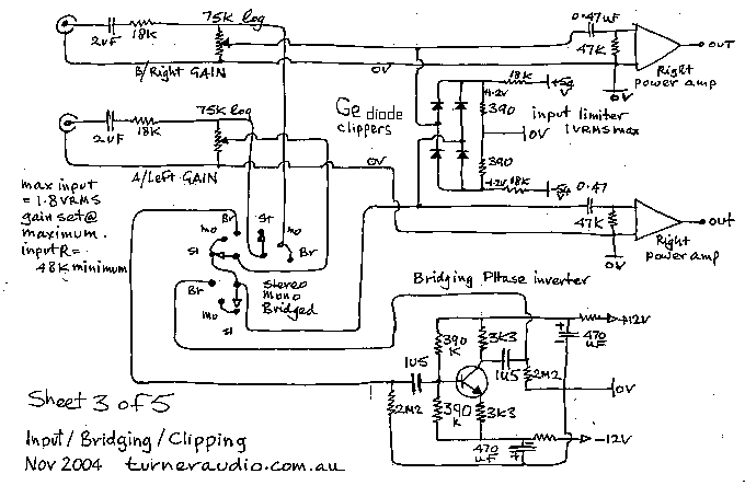
This shows the arrangement for switching the amp from stereo to
dual mono to bridged.
Fig 4.
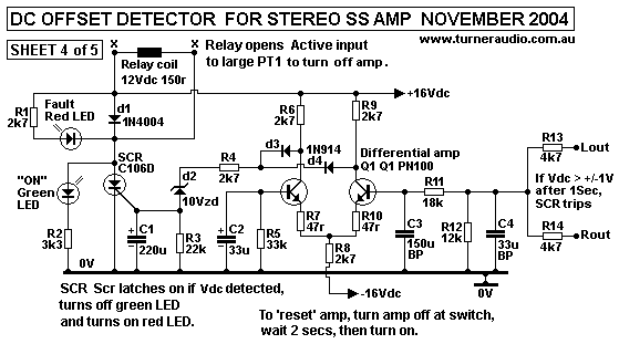
if ever there is a failure of a device and the fuses
don't blow, 50V dc fed into an
8r0 woofer will have it in flames within 30 seconds!
Fig 5.
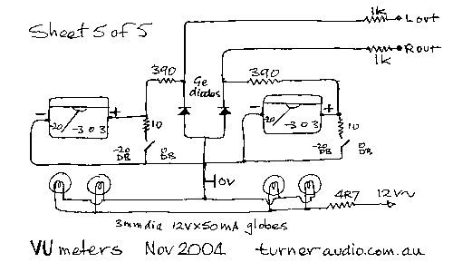
This is my improvised meter schematic using existing meters.
They tended to stick a bit, and I didn't
waste time trying to fix 30+ year old meters designed by
accountants. Originally they were horribly
bouncy and very badly calibrated. They were never designed to
indicate real power regardless of load.
They are very useful though, like a fashion statement by a fish
swimming around in the sea with a pink
umbrella.
To build a circuit that indicates power rather than just voltage
takes a little more work.
The above schematic has some partial ability to indicate voltage
logarithmically.
Amplifier voltage meters should be logarithmic. This means that
they are calibrated for full output
voltage level into 8r0 for full scale, so then for 1/10 of the
maximum power the meter needle should
be about 1/3 of the way across the dial, and for 1/100 of max
power the needle is at 1/10 the
way across the dial.
After all the work I did on the Phase Linear I concluded that I
would never again use BJT output devices.
And I will never again reform such a recalcitrant amplifier such
as one of these ancient horrors that
would ideally be better used as a boat anchor.
So if you have a bunch of dead Phase Linear amps, don't ask me
to fix them, I retired in 2012.
I found there was more work involved with reforming a wayward
and fault ridden Phase Linear than
building a brand new amp, and because it was a repair job, I
could not charge much for my work.
Back to Index Page 


