SE 35 WATT MONO BLOC
This page edited June 2017..
2 x 35W amps on bench, 2004.
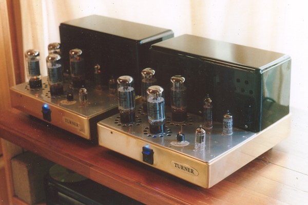
These SE35 mono blocs were built for a very discerning customer
who wanted high levels of undistorted
sound with two large modern floor standing speakers, the VAF I-66,
rated for about 90 dB/W/M.
He was amazed at the precision and detail these amps offered.
Most "high power" make 22W with one large expensive single triode
such as 845, 211, GM70, 13E1 and for
higher Po there are 2 paralleled 845 for up to 55W. I found I
could easily get 35W from 4 x EL34 or 6CA7.
I did build one 60W SE amp with 6 x 6550 all paralleled. I did not
meet many people who needed more than
35W per channel, but I did work for those few who wanted more
power, but who did not need it, but who had
the money to pay for it.
The SE35 have a brass chassis with aluminium top plate. Power
supply PT and OPT are within a steel box
behind the tubes. The steel gives some magnetic shielding to
circuitry under tubes at amp front. The top-plate
and the bottom cover plate is well drilled for ventilation to
allow rising cool air around the output tubes.
No printed circuit boards are used, so there is no obstruction to
easy air flow so necessary to keep all tube
amps cool.
All transformers use GOSS + I lams with very generously sized
cores to prevent high temperature rise in
the PT ( power transformer ) and to get blameless bass performance
from the OPT ( output transformer )
Without any NFB, the OPT response at full power to the rated load
is from 20Hz to over 70kHz. The response
with NFB is shown in the graphs below. Weight is approximately
25Kg per chassis.
The power supply has Si solid state rectifiers for B+ with a
simple CLC filter for the B+ anode supply Vdc.
There is a shunt regulated +Vdc screen supply. The output tubes
have Vac for heaters but input tubes have
R&C filtered DC heaters.
Cathode biasing with separate R&C networks on each output
tubes gives good automatic bias current regulation
and there is no need to use accurately matched EL34 or 6AC7. There
are no bias adjustment screws which will
confuse many owners.
The input tube is SET 12AU7 with both sections paralleled. Driver
tubes are EL84/6BQ5 strapped as a triode,
in SET mode. The right front tube is a 12AX7 in cathode follower
mode to act as a buffer after the input signal to
drive a switchable frequency low pass input input filter to allow
variable cut off frequencies for bi-amping.
This buffer stage is not needed where bi-amping is not required.
It was found to be sonically transparent.
The original owner wanted an 8585 for bass and SE35 for midrange
and treble. The input of 8585 had a variable F
filter to remove midrange and treble. The SE35 had switchable F
filter to remove bass so that the effective power
ceiling for SE35 was made much higher without having to produce
bass signals. Thus intermodulation distortion
is much lower. However, although bi-amping is ideal in theory, I
found that for the listening levels wanted there was
no need to bi-amp, and SE35 or 8585 could be used alone for
everything that was needed for a large full range floor
standing speaker.
The input cathode follower also allowed use of a "passive" preamp,
which in this case was a Vishay high grade
switched resistance attenuator. There are virtually no HF losses
because input resistance of the cathode follower
is so high and with very low input capacitance.
The schematic shows some unusual techniques to reduce the normally
very high THD measurements with any
SE amps to levels more normally seen with good PP amps, especially
within the first 10W.
THD is less than 0.1% at any load between 3 and 12 ohms for up to
10W. Most other SE amps cannot achieve this.
I am using low amounts of local cathode feedback in the output
stage in what is called the "Acoustical connection"
and low amount of global negative feedback from the speaker
secondary to the input triode cathode. The total
amount of local and global NFB is less than 20dB.
A more detailed description follows with schematics.
Sheet 1, Power amp schematic.
Sheet 2, Power supply.
Sheet 3, Protection.
SHEET 1 - 2004, POWER AMP SCHEMATIC.
This schematic was used in 2004. In June 2017, have re-drawn the
previous untidy hand drawn sketch from 2004.
I have included slight increase to Iadc in V2 and V4 with a few R
values changed to allow this.
Input is fed into the high input resistance of V1 12AX7 cathode
follower with its output driving a switchable cut off
low pass first order RC filter with F settings for -3db at 7Hz,
50Hz, 140Hz, 510Hz, and 1,020Hz.
R6, R7 form a divider to set the sensitivity of the amp to match a
bass power amp, so that equal voltages are sent
to bass and treble speakers designed for use with a normal single
amplifier.
The tube line up in the power amp is V2 = 2AU7, V3 = 12BH7.
12BH7 did work well, but 6BQ5 / EL84 works and sounds
better.......
SHEET 1- 2011, power amp schematic.
The 2004 power amp schematic with adjustable high pass filter was
revised in 2011 because of interest by DIYers
around the World. Just about everyone wanted the amp without a
built-in HPF.
I have re-drawn the schematic in 2017 using Arial font and have
made a few things easier to understand.
V2 is a paralleled 12AU7 with a transistor MJE350 for anode dc
supply with extremely high ac impedance aka
CCS, or constant current dc supply. This minimizes V2 THD,
important because any 2H will *add* to the 2H of
the output stage. V3 is EL84 in triode with 50H L1 + 8k2 to feed
Iadc. This gives gain of about 18, near the
triode µ for EL84. The EL84 Ra is about 2k2 and it works better
than 12BH7 with higher THD, Ra = 3k0, and
gain about 11.
V4 to V7 are 6CA7 shown in picture but can be EL34.
The 4 x EL34 having Ikdc = 270mAdc, thus generating
Ek = about +18Vdc with total of 4 parallel Rk = 60r plus 12.5% of
primary wire resistance, about 6r, so 66r total.
4 x 6L6GC / 6550 / KT88 / KT90 / KT120 could be used, but for the
same Ea = +350V and Eg2 = +270V, the
bias between grid and cathode must be larger for the same Ia as
for EL34. Thus a -15Vdc supply with an adjust
pot could feed bottom of resistor R17 68k. This allows -Vdc grid
bias estimated at about -32Vdc, for the same Iadc.
The existing Rk + Ck will not need to be changed and will work to
self regulate the Iadc.
if 6L6GC are used, idle Iadc and Ig2 should be kept the same as
for EL34. For 6550-KT90 etc, total idle Pda and
Pdg2 for each tube not exceed 26W, for 104W for the 4 tubes. For
total 104W, expect 96W for Pda, Iadc = 274mA,
with Pdg2 about same as EL34. The OPT primary will withstand the
higher Idc. The load for max Po with Ia =
274mA is 1,150r, with secondary loads becoming 1r2, 2r6, 4r6, 7r2,
10r4. None of these loads are any better
than with Ia kept as the schematic shows, so the idea of change to
6550, KT88, KT90, KT120 would
be an act of vanity, IMHO.
The OPT I made For SE35W has :-
Wasteless E+I lams, T44mm x S62mm, L66mm x H22mm. I recorded air
gap = 0.87mm
using 0.43mm air gap material across the whole 132mm x 62mm area
between E and I, because
there are two gaps in the ML path around each winding window.
Interleaving pattern is basically 4Sec x 3Pri sections. Primary
has 16 layers at 122tpl of 0.45mm
Cu dia wire, 0.516mm oa dia, with 3 anode winding sections of 5
layers, 4 layers, and 5 layers.
These are wound between 4 Sec sections with a total of 6 layers of
62tpl of 0.9mm Cu dia wire.
The 4 Sec sections are :-
Section 1 = 1 layer of 2 x 31t,
Sections 2 and 3 = 2 layers of 62t each,
Section 4 = 2 layer of 2 x 31t.
Between the two layers of Sec sections 2 and 3, there is one layer
of primary winding devoted to
12.5% of local cathode feedback in the output stage.
So the wire layer build up in bobbin can be described :-
S-p-p-p-p-p-S-k-S-p-p-p-p-S-k-S-p-p-p-p-p-S.
"S" = Sec layer, "p" = primary layer in anode circuit, "k" =
primary layer in cathode circuit.
0.4mm polyester insulation is between all S to p interfaces, and
0.05mm between p to p layers
and also between S to k interfaces. The placement of CFB windings
between sec layers was an
experiment which worked well, but no better than where I more
commonly placed CFB layers
between grouped anode layers a Sec layers and with the same 0.4mm
insulation.
Total RwP+S = 10.3% of anode load.
Rwp is 4.5% of total Rw, RwS is 5.8% of total Rw.
RwP for 16 layers of anode and cathode windings = 62r.
Where OPT is strapped for 1,952t : 3 // 124t for nominal 1,239r :
5r0 loading, the Sec RwS
= 0.326r, which appears at primary as ZR x RwS = 247.8 x 0.326r =
81r, so total RwP+S at
primary = 62r + 81r = 143r, and the total anode load = nominal
1,239r + 143r = 1,382r.
Total winding loss = 100% x 143r / 1,382 = 10.3%.
So where there is 35W at output at Sec, the tubes
make 38.5W to primary, and 3.5W is lost as heat in the winding
resistance. This is unavoidable in all
transformers, and can only ever be minimised, and to get lower
losses involves exponential increase
in OPT weight. Resistance does not cause THD or IMD in this case,
and 10% loss is actually quite
a good result for SE OPTs which always have higher Rw losses than
PP amps where good design
principles have been used. The Primary idle current density =
1.51A / sq.mm, less than 2.0A, so quite
OK, with 3.5W of heating in the primary wire which is within a
large enough volume of core to not give
high temp rise. Primary RwP loss is less than Sec RwS loss which
is correct for SE amps where
high Idc flow is in all Primary turns.
The nominal anode load is about 1k3 for maximum Po, but can vary
between 900r and 2k6 with speaker
load variations. Nominal secondary load = 5r0 for maximum power.
So in effect, each of the 4 output tubes
sees anode load = 5k0.
2 primary layers of 16 total layers of primary are used in series
between cathode and 0V to give 12.5%
local CFB to EL34. This reduces pure pentode THD from about 9% at
35W to 2%, and reduces effective
anode resistance to less than triode. The OPT CFB is equivalent to
about 8dB local NFB with 5r0 at output.
Global NFB = about 10db, so total NFB with 5r0 output load = 18dB.
The THD of output stage is mainly 2H and is "cancelled" by THD
produced by triode driver stage.
This is a natural phenomena due to the relative phases of 2H of
the two stages, and their relative levels
between low Po and maximum Po.
The output EL34 with CFB require up to about 45Vrms drive to their
grids, and 2H produced by EL84 or
any other triode driver will have similar % level. The inevitable
2H of driver reduces 2H in output EL34,
and 2H at amp output is reduced to very low levels. This is not an
easy issue to fully understand.
Most SE pentode or beam tetrode tube output stages may be used
with a range of loads below and above
the "nominal value RL", ie, in this case, 5r0. For RL below centre
value, 2H produced has the same relative
phase as a triode. The lowest usable RL with an SE amp is 1/2 the
centre RL, ie, 2r5 in this case. Max Po is
less than 35W, and THD may be higher but it is where max 2H
cancellation occurs. For RL well above 5r0,
the EL34 make oppositely phased 2H, so no cancellation occurs.
However, the higher RL make EL34 subject
to much more dB of local CFB so THD with 15r0 remains low without
reliance on 2H cancellations.
While strange behavior occurs with 2H production relative to load
value, there is maximum 3H with low RL,
and 3H declines gradually as RL increases between usable RL
of 2r5 to 15r0. This 3H is unavoidable in
SE pentode and beam tubes, but it is not any higher than what
occurs in a class A1 PP amp. The 3H is also
much reduced by the CFB connection. 3H generated in EL34 output
stage cannot be cancelled by 3H in
EL84 triode driver stage 3H is so low.
Now in all TRIODE SE amps using a triode OP tube such as a single
300B or triode strapped 6550, KT88
the 2H Vac produced by each stage has the same relative phase
between 2H and fundamental frequency
for all RL values. Therefore 2H cancels with all load values. But
a typical triode output stage has no CFB
and typically produces 5% 2H at near clipping. The triode driver
stage may produce about 2% 2H when the
OP tube clips. If you built a driver stage to make 5% 2H, it would
also produce much other HD, and IMD,
so its pointless to make a non linear driver stage just to make 2H
cancel.
So with a well functioning SE triode driver stage, its 2% 2H is
amplified by the OP tube to produce an
oppositely phased 2H signal so that overall 2H at output = 5% - 2%
= 3% 2H. This is not a bad phenomena
and occurs in all SET amps. There are some low level IMD harmonics
products called "second order products"
produced, but they remain low enough to be ignored in this
discussion.
With CFB used in a pentode or beam tube OP stage, the same
cancellation occurs where the OP tube 2H is
the same phase relative to fundamental F, and for RL below the
centre value. But the CFB reduces the OP tube
2H to say 2%, and the driver tube produces 2% 2H, and at this
point the overall 2H level can be close to zero.
It never ever reaches zero because slight relative 2H phase
differences between driver and OP stage.
But the amount of natural 2H cancellation is highly useful in
bettering fidelity.
Graph 1. 2H Cancellation.

These graphs of RL vs THD are difficult to understand because
nobody else bothers to ever draw such graphs.
The thickest lines are a set of 4 curves for CFB operation at
power levels between 0.25W and 16W.
There are 4 thin line curves for the same OP tubes used in SEUL at
power levels between 0.25W and 16w.
At 0.25W, SEUL amp produces 0.15% THD into 2r0 which reduces to
0.08% for 4r5, and to 0.04% for 16r0
for 0.25W.
At 0.25W, the CFB amp produces 0.1% THD into 2r0, which reduces
rapidly to 0.014% at 4r5, and then rises
to equal the SEUL level at 7r6, and rises further to 0.09% at
16r0.
Now for both SEUL and CFB amps, the THD for 0.25W is less than
0.15% for any load between 2r0 and 16r0.
This is a good result for any SE amp. Most of the HD will be 2H in
general, and resulting IMD is negligible.
But the CFB amp has more reduction of 2H with RL between 3r0 and
7r0 and for a nominal 4r0 speaker,
THD for the CFB amp = about 1/4 of the THD from SEUL amp.
The null of THD seen in CFB curves is all due to 2H being very
much reduced with the remaining HD being
mainly 3H. Other odd number H are very low at 0.25W and 1W levels
and these do not rise significantly until
10W is reached. The CFB amp gives less THD even with a nominal 8r0
speaker.
Most of the power in the audio band is between 100Hz and 500Hz
where often there is low speaker
impedance and high current, and it is in this region the CFB amp
copes better than the SEUL amp.
The other benefit with CFB is that most of the THD reduction
occurs in the OP stage, and any signal fed
back to an earlier input stage has less THD content, so less IMD
products are produced by non-linearities
in the input or driver stages.
The curves above were recorded from the 2004 amp version with
12BH7 driver. The amount of 2H in any
chosen driver tube such as 12AU7, 6CG7, 12BH7 or EL84 will vary,
and this changes the position of the
nulls on the curves. As the driver tube becomes more linear, the
null position occurs at a higher RL.
The lower THD and IMD with CFB does not seem to fully explain the
improved fidelity heard from the SE35.
The use of the EL84 probably contributes much to the sonic
fidelity because it produces such a small amount
of THD/IMD compared to other driver triodes with lower Ia. I have
found both EL84 and EL34 in triode to be
extremely fine driver tubes. I've found the use of EL84 as PP
driver stages in my PP amps to be superior to
other smaller twin triodes. It was for this reason that I changed
from 12BH7 to EL84.
In 2009, I made a headphone
amp with EL84 in triode with a small OPT and driven
with 6CG7.
The amp was integrated, and could be used to be a very fine line
level preamp.
The HD spectra for 4r5 has some 2H, but it is mostly 3H. There is
also 4H, 5H, etc in diminishing quantities
which only increase greatly at the onset of clipping. The higher H
artefacts are mostly hidden from view on an
oscilloscope at below 2W which covers most listening. In most SE
amps the 2H is usually overwhelmingly
dominant, often being more than 15dB above the levels of any other
harmonics, so that where 2H is 0.1%,
3H will be 0.02%, with 4H, 5H being buried in the noise floor of
the amp.
Distortion cancelling is frowned upon by some because they say the
distortions of a driver tube are
themselves distorted by the output stage thus there is an
increasingly complex mixture of THD and IMD
harmonics produced compared to just trying to have a fairly linear
driver and normal output tube with fairly
high THD. My approach was build the driver stage so it is
naturally linear, and at least no less linear than anyone
else might achieve with resistance dc load. One might deliberately
set up the driver tube to generate higher
2H to better cancel 2H of the OP stage, but this is not the best
approach. The 2H cancelling I achieve is a
benign by-product, but is not deliberately created.
2H distortion voltage cancellation occurs in every SET amp ever
made. Very little is ever said about it, but in
SE triode amps where the output tube is a 300B or 845 without CFB,
and where the driver must generate
high Va to power output tube grids, there is a substantial amount
of 2H made by the driver triode.
This cancels a portion of the 2H made in output tube. A 300B may
have Va = 180Vrms with THD = 6%, and
need 50Vrms at grid from driver triode which may make 3% 2H. The
resulting 2H at 300B anode = 6% - 3%
= 3% 2H overall. But if the driver makes some 3H, maybe 0.7%, and
300B makes 1.0%, then total 2H at
output = 1.7%. Usually, triode 3H % is very low at normal
listening level.
If anyone wanted to use 4 x 6550 or 4 x EL34, all in triode mode,
the max possible Po = 32W from 6550
and 25W from EL34, and there would be similar levels of THD to the
SEUL levels shown in the above graph.
In triode mode, there is no need for CFB which becomes ineffective
with the low triode gain, about equal to
4dB of FB.
Graph 2. THD vs Vo.
The THD graphs with CFB were measured in 2004 for various values
of RL above 3r0. THD is lowest with
loads between 4r0 and 6r0. At 1W for 4r0 or 5r0, 5 ohms THD <
0.032%, This is about 20dB lower than in
most other SE amps where it may be 0.32%. THD with 3r0 is higher,
but would be *much* higher than what
is shown if there was no 2H cancellation between the driver and
output stages.
The difference of THD between SE35CFB and SEUL 25W 13EI amps can
be seen here.....
Graph 3. SEUL and CFB THD compared.
The SEUL amp with one x 13EI tube is a very good sounding
amplifier. But like all SE amps, there is
some THD, and it has a typical amount shown above and with about
15dB of applied global NFB.
The SEUL graph would be also typical for many pure DH triode SE
amps, or those using triode strapped
pentodes or beam tetrodes which might use say 10dB global NFB.
The SE35CFB also sounds well, perhaps better, but its performance
with 5r0 is so much better. At low
Po for most listening. The SE CFB amps have 6 times less THD, and
THD which is about the same as a
good PP amp with the same amount of total NFB.
Graph 4. Frequency Response SE35 at full power, 5 ohms, and
-6dB, -15dB.

The top graphs show the response of the amp with 5 ohms at
clipping, and notice that some bandwidth
limiting occurs at extreme LF and HF, but -3dB points are 14Hz and
32kHz. The responses are with full
amounts of NFB. The top graph has the input filter switch set for
zero LF attenuation.
More bandwidth becomes available away from near clipping as shown
in the -6dB line, or 9W.
The bottom graph at -15dB low levels show the frequency peaking
effects of pure capacitance loads
between 4uF and 0.33uF, along the right side of the -15dB line,
and there is virtually no peaking below 20kHz,
showing that the amp can drive any ESL load, and that without any
resistance, any pure C load will not cause
HF oscillations. The line without peaking under C peaks is for a
pure 5 ohms. The peaking with pure C loads
is considerably reduced if there is also a parallel resistance
with capacitance load. The response of the low
pass filter is also shown for different switch positions.
SHEET 2. SE35 PSU.
The above PSU schematic gives close to what is needed for the 2004
and 2011 amplifier schematics.
The PSU does not use tube rectifiers because they do NOT improve
the sound.
The CLC B+ filter with C1, L1, C3, C4 will give excellent low
noise at the OPT connection = 3.6mVrms,
100Hz even without C2&R1.
This depends on L1 = 1H minimum and it should have Rw < 40r so
that heat in L is less than 3W for a
core size of T = 25mm, H = 25mm. The choke may be larger with more
L but Rw should be kept < 40r.
The C2 and R1 combine with L1 to make a 100Hz damped parallel
resonant network which increases
100Hz
attenuation about -12dB so that with only 1H, Vripple <
1.5mVrms. L1 with C3, C4 have resonance at 5.2Hz,
low enough to not cause too much emphasis of LF mains noise,
caused by so many other users switching
electrical gear on and off in your street or apartment block.
Since the original 2004 PSU schematic was drawn, dc has been
applied to the 12AX7 if used and 12AU7
input tube heaters to ensure a super low noise floor. There is no
need to use DC to the driver stage but
anyone is always free to do this if they like to trim values of
series resistors in the schematic.
SHEET 3. Active protection and delayed B+ turn on for SE35.

I repeat text on the schematic :-
DELAY. After turn on there is a slow rise in voltage at C2 fed by
current through R2 so that after 25 seconds
current will flow through the 8.2V zener diode and turn the
Darlington pair of Q1 and Q2 to quickly close a relay
in series with the HT of the power transformer.
PROTECTION. The four cathode dc voltages are reduced by
dividers and each fed through 1N4007 to the
base of emitter follower Q3. If one or more of the Ek cathode bias
voltages rises due to increased cathode
current, a sample fraction of Ek is applied through diodes to the
base of Q3, which is an emitter follower buffer.
The emitter voltage at Q3 will also rise and if that exceeds the
threshold for forward current flow in 3 series red
LED, d6, d7, d8, then the SCR gate voltage will rise enough to
latch it on. Once turned on, the SCR stays turned
on regardless of the Ek. And when turned on, the SCR anode has low
resistance to 0V thus draining voltage
charge from C2 so that Q1 and Q2 are turned off and relay coil is
denied current. Relay points open, thus HT
winding is opened and B+ reduces to near 0V. The d5 red LED is
turned on to indicate there is no B+ present.
The EK voltage required to trip the SCR is +27Vdc. Vac at cathodes
is filtered away by networks 47k, 15k and
220uF so that AC signals do not trip the SCR. If the amp is turned
off at the mains switch, the +18Vdc rail in
the PSU will rapidly reduce to 0V because it is loaded with the
low resistance filaments of input tubes.
So then the SCR quickly becomes "unlatched" and the amp may be
turned on again to "reset" it. If the SCR is
soon tripped again after the 25second delay then something is
wrong with an output tube.
If any output tube misbehaves, there will not be any smoke in your
lounge room, or any expensive repairs
to output transformers. The reason for active protection rather
than reliance on fuses alone is because if only
one tube were to become saturated with say 300mA of idle current
then the mains fuse will not blow.
So the active protection works well before an errant tube can
become saturated. The circuit will work when the
Ik current in a single tube rises from the normal 62mA to 100mA.
Since 2006, the protection circuit fitted to SE35 has earned its
keep. Owners cannot resist the urge to buy
expensive NOS EL34 which they think sound will better. While this
may be the case, some NOS tubes that
have spent perhaps 40 years sitting on a storage shelf may have
developed tiny defects in the glass and after
being used for a week, a month, or 6 months, the defect slowly
allows air into the tube and the tube loses bias
control and tries to conduct excessive Ia before it finally self
destructs, To avoid the pyro-technical display and
collateral amp damage, the amp is turned off well before faults
become excessive. Protection also guards
against grid connections to tube sockets going open, owners
turning up volume with a shorted speaker lead,
or coupling cap failure.
Back to index page