QUAD-II FORTY RE-ENGINEERING.
Everyone interested in tube amps may have seen old 1950s Quad-II
monoblocs or
pictures of them because over 100,000 amps were made in UK and
they were bought
by BBC in large numbers for their many studios. They used two EF86
and two KT66
and a GZ32 rectifier and could make about 15W to 22W with speakers
from 32r0 to 8r0.
The OPT had two links under chassis to adjust the speaker load
match for 16r0 or 9r0
which have the same RLa-a load for tubes = 3k9 for class AB1.
Many users of these amps became confused when needing to change
the OPT links
after purchasing different Z speakers.
Most speakers in 1960 had nominal Z = 15r0, and it did not matter
much if OPTs were
set for 16r0 or 9r0, good sound was possible. Quad ESL57 were sold
to buyers well
after Quad-II began to be sold, and the very variable Z for ESL57
could be driven by
Quad-II fairly well. There is more about
this at quad2powerampmods.html
In 1950-60, "Normal" dynamic speakers with cones and domes and
voice coils were
mostly rated at 16r0 across the AF band. Quad-II amps powered
them well because
speaker sensitivity was usually over 93dB/W/M ( at 1kHz ) and
very little power could
make music very loud, ( eg, Tannoy dual concentrics. )
With 16r0 speakers, and OPT links set for 16r0, the amp produces
over about 22W
in class AB1, and the anode RLa-a load is about 3k8. If the OPT
links are changed to
match 9r0, then the same 16r0 speaker makes anode load = 6k8,
and 18W in class AB
is possible with initial class A at 10W, and this gives best
sound and best technical
operation but the slightly lower maximum Po did not matter to
most ppl in small houses
with small rooms and sensitive ears. The SPL at seats in concert
hall averaged 85dB.
Two speakers each rated at 93dB/W/M need only 0.075W each to
make 85dB SPL.
But since 1955, most speakers sold to most people are now
between 4r0 and 8r0 and
average is about 6r0. Almost none are above 12r0. If you Google
this issue,
many speakers which do have average Z = 6r0 will have that
average between 100Hz
and 1kHz, but the Z varies between 4r0 and 20r0.
The average sensitivity of modern speakers has fallen from about
93db/W/M at 1kHz to
to about 87dB/W/M at 1kHz so today's speakers require 4 times
more power to get the
same SPL as in 1955. But modern speakers have less THD, IMD and
box and have
wider bandwidth so they make better bass and treble for the same
Vac applied than in
1955, except for the best brands at that time which were too
expensive for most ppl.
Best bass can only come from floor standing 3 way speakers. The
nominal Z of many
speaker drivers may be 6r0, but the crossover filters may cause
minimum Z to be 4r0
around the crossover regions. Nominal 4r0 speakers are not well
handled by Quad-II
amps because their OPT were not designed to allow the best
linking of secondaries to
suit 4r0 speakers.
In 1990s, there was high interest in Quad amps and and all Quad
ESL speakers, and
Quad had made a large range of both by 1995, but of course
nostalgia does not always
translate to being profitable, and no new Quad tube amps were
available to match the
new demand for them in 1990s. The founder of Quad, Peter Walker
died, and amp
making process was purchased by Chinese entrepreneurs who had
access to Chinese
labour which was -20dB cheaper than UK labour.
Mr Andy Grove had become a prominent UK guru on amps and was
hired by Chinese
to design a re-issue of tubed Quad monoblocs. The Quad-II-Forty
was born. Someone
must insisted that Andy make the amps just like original but
with KT88 instead of KT66.
So almost the same schematic is used for the Quad-II and
Quad-II-40.
So just when there was a wonderful opportunity to make a better
amp than Quad-II,
it was blocked by the stupid idea that the past mediocrity must
be preserved for the
future.
Despite the shortcomings of the 40, they were much welcomed. I
could only get 32.5W
max with sine wave testing to clipping. Maybe 40W was possible
in wave peaks before
the inevitable sagging of B+ and charge build up in cathode bias
networks. The 40
has 2 x KT88 output and can have any type of 6SH7 as input /
drivers and a 5U4
rectifier.
The Quad 40 and Quad-II have cathode biasing but the 40 has
separate cathode R+C
networks for each KT88, which is a sensible departure from
original biasing.
The 40 chassis was larger, PT and OPT cases bigger. But just
what is within the PT and
OPT cases is anyone's guess, and the REAL truth of that has
always remained obscure,
and my guess is that whatever is inside the cases came from
stocks of spare parts for
obsolete Chinese military gear. The 6SH7 in the Quad 40 were
metal case versions
made to withstand the blast of a grenade thrown into a radio
room. GE notes say 6SH7
have a hum problem for audio, but later types, 6SH7GT was free
of such problems.
6SH7 was a very good pentode and far better than EF86 but when
used as they are with
such low Iadc, both tubes are feeble, and the pair used cannot
match the performance
of having paralleled 6SN7 plus 6SN7 in LTP mode.
Quad-40 Paintwork looks nice, but paint is not as rugged as
original Quad-II.
I had a few customers who had lots more trouble with Quad 40
than they'd had with
Quad-II.
Most of the design shortcomings of the original Quad-II were
included in Quad 40.
Quad 40 has a PCB with poor quality and little regard for how
all things are spaced and
in 1990s the Chinese who made tube amps had no idea of the
traditions of good tube
amp circuit design in western nations where design was always
done by men with maybe
40 years of experience. In the Chinese system it seems they had
no idea of prototype
development where a prototype is built, and is then allowed to
be criticised and then a
second prototype is made, and criticised again, and the final
prototype is allowed to be
mass produced. Much modern design is done by computer programs
and simulation, and
then produced, and the makers hope there are not too many
criticisms by public which
could reduce the share price and ruin sales numbers.
The Chinese don't like losing face, and they don't like ppl
telling them they have
succeeded in making a POS product. But many western companies
and Chinese
communist + capitalist ppl are arrogant, and they cannot fool
me. I should not be able
to make any valid criticism of the Quad 40, but these amps are
begging to be given a
poor report.
Since 1995, Chinese have improved a bit, and if I bought a 40W
Chinese made soldering
iron 1995 for $20, it would last a month, maximum, Australian
made irons lasted a year,
but were $60. Then later, by 2003, the Chinese irons lasted
years and years, and their
alloy used for tips did not erode, and they remained at $20.
That drove all the western
soldering iron companies out of business. Chinese have a space
program, I have seen a
report on news about a 55km long bridge in China, and it seems
to me they now do know
a lot which appears to be enough. Isee they have fast trains,
and are able to do huge
things properly, and the buyers do not have to pay a price which
includes taxes and the
vast profits of western business and payments to greedy share
holders.
Well, the first Chinese made soldering irons had to be better
than previous irons because
regulations were imposed on solder to eliminate lead to stop
lead pollution leaching into
the environment. Lead free solder needs higher temperature. But
for repairs, I still use
Pb-Sn solder and I run the Chinese irons with 180Vac not 240Vac,
using a PT with
switched secondary Vac. Most likely, Chinese irons are designed
for 220V, and those
exported to Australia are 220V rated, but they sure run too hot
with 240V, so my 180V
is wise, and I can turn up to 240V where extra heat is needed to
solder wires to chassis.
When done, I switch down to 180Vac.
Chinese made clothes and shoes have become better than western
mades, and much
cheaper, and the "leather" may not be real, but then not so many
animals are needed
to supply the present huge demand for 1,001 things.
The Chinese ceramic tube sockets in Quad 40 are The Worst I have
ever seen and
when rebuilding these amps, replace all of them. The ceramic is
OK, they have known
how to make good ceramics for at least 3,00o years, but the
metal in pin grippers is
horrible alloy which bends so the gripper loses its spring
tension and tubes are not
well anchored to the socket. It is not immediately obvious, but
after plugging and
unplugging a few times and swaying tubes to side the grippers go
loose, and must
be bent tight, and after that is repeated enough, the grippers
break. The tube sockets
made since 1995 are much better. I can only guess they found or
stole the recipe for
metals in tube amps and the copy ended up better than the
original.
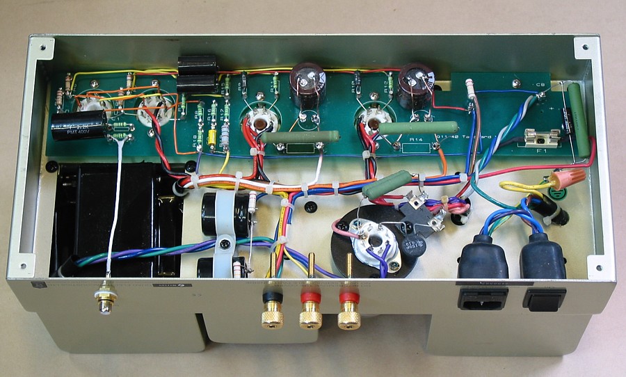
When you take off the bottom cover of Quad-II-40, you see the
PCB is crammed in
some places and not in other placed where there was much room
available.
There are 4 green hot running resistors swaying in the breeze
off long leads. The
left one is going brown from far too much current. The Chinese
KT88 were not so
good in 1995. There is more disappointment to be found as one
looks below the
surface.
Fig 1. Original condition of Quad-II-Forty under chassis.
Now this amp had smoked and blown a fuse a few times and made
noise.
The Quad-II-40 does have separate R+C networks for each KT88
cathode.
The board shows a small rectangle where the Rk should be, but
they needed a
larger higher watt rating type, and away from the board which
degrades with hot
resistors nearby. Why not decent turret strips and NO PCB? In
this picture,
I have already replaced the tiny cathode caps with larger 270uF
rated for 200V
and high ripple current.
The original green cathode R = 390r, and are rated for 7W. Heat
with 100mAdc
= 3.9W. They should be ceramic types, and better mounted between
two turrets
so they cannot swing about much. Touching the 390r, you get a
burn; they are too hot.
The best way to prevent so much wasted heat in Rk in this case
it to Eg2 at say
00Vdc below B+, and not have such high Idle Iadc, OR, reduce the
Iadc by making
Rk higher value. These original amps have KT88 idle Pda too
close to the Pda
rating of 42W. Only fools will idle KT88 at over 35W Pda. They
read 42W, assume
that is OK at idle, It just is not, and maximum safe idle Pda =
0.6 x max Pda = 25.2W.
Notice the thermistor used to slow down heating of the 5U4
directly heated cathode.
This shows poor knowledge of tube properties during warm up.
KT88 take about 20
seconds to warm up enough to reach near the settled idle
condition. 5U4 with directly
heated cathode takes 3 seconds. But the thermistor plus a series
resistor which is fed
by 6.3Vac transformer winding does not slow down emission in 5U4
very much so the
B+ soars to +546Vdc anyway, and series B+ caps are a necessity
to avoid having
excessive Vdc across any of them. Most cathodes or heater
elements for tube diodes
are meant for 5.0Vac but the 6.3V winding shows the PT was
chosen from ex military
spare parts as being "near enough" The HT winding of 390V-0-390V
is not right, and
could have been 340V-0V-340V and a 5AR4 / GZ34 would have been a
better
rectifier tube. Nobody at Quad will agree with a single sylable
I write though.
But the build quality is better than some other much worse
Chinese amps I had to
work on, some made in Hong Kong, and sold online for $1,200.
The production cost to the Chinese is probably < $200 using
what is virtual slave
labour, yet you pay many thousands for a pair in the shops in
London or Sydney.
There is ZERO NEED for a tube rectifier, other than to satisfy
ignorant tube amp
enthusiasts who like to pay for 1955 technology which does
nothing to improve the
music, and nothing to give best reliability. Sure, the audio amp
tubes do work well
for music, but the tube rectifiers give ZERO positive
contribution. Silicon rectifiers
allow for far more reliable working without the heat wasted by
the tube rectifier, plus
the Si diodes allow lower Vac for HT winding with a doubler or
bridge and they offer
far better natural Vdc regulation than any tube rectifier can
offer. The use of high
value electro caps is then possible which allows very low ripple
in B+ supplies.
On the right hand end of PCB, there are two small size electro
caps in series poking
down under PCB into spare space inside PT box. I'd say the
chassis and transformer
cases were built before gathering all the parts to be used.
Those transformer cases
contain too much fresh air.
If these caps need replacing, the PCB board must be lifted out
to get access to el-caps
and repair is hugely difficult when it should not be. The box
for the choke on chassis
top has L > 10H and Rw = 375r, and this acts to filter the
fixed B+ applied to screens
of KT88, and for B+ of input stages, just the same method as
used in old Quad-II.
The choke box is bigger than it needs to be, and the anode B+
was not well filtered,
also like old Quad-II, so best class AB operation is not
possible.
Fig 2. Reformed Quad-II-Forty under chassis.
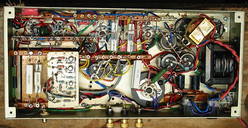
Fig 2 shows what I ended up doing with two Quad-II-40 monoblocs.
PCBs were removed to rubbish bin. Connector strips
installed, using 10mm x 8mm
hardwood rods with 4guage c/s brass plated cupboard hinge screws
as terminals at
10mm c-c. The soldering heat cauterizes the timber and releases
splitting pressure in
2mm drilled holes. But screws remain well fixed and in 500years
integrity will be fine.
The wood strips are well varnished. There are few tag strips
worth buying now and
those made now have inferior phenolic strip material and have
very thin metal, and
Chineezation of such things that used to be good means quality
is binned.
I didn't trust the existing coupling caps so I used red-box Wima
630V caps glued to
chassis with Selley's Silicone 401, acetic cure, good for 200C,
and should last
indefinitely, based on experience since 1994. All tiny sized R
were replaced with 3/4
or 1W metal film.
At bottom left, I fixed a board plus terminal strips for some
hot resistors and for
the protection board with a circuit to turn off the amp is too
much Idc flows in KT88.
Top right shows 7VA PT to power the protection circuit.
At right side there is an added choke to properly filter B+ at
the OPT CT.
Below this choke is a relay to turn off mains if KT88 conduct
too much Idc.
The new schematic is entirely different to anything Quad made.
Notice the 1.6mm dia copper wire 0V rail running above tube
sockets.
While 2 original electrolytic caps were retained, others with
larger C values were
added. DC is applied to input tube heaters.
Fig 3. Schematic for reformed Quad-II-40.
Fig 3 is the new amp schematic.
KT88 have revised operating conditions with :-
B+ = +420Vdc, Ea = +377Vdc, Ek = +43Vdc, Iadc = 62mAdc, Eg2 =
+407Vdc,
Ig2 = 4.6mAdc, Ikdc = 66mAdc, Rk = 630r, Pda+g2 = 24.9W.
The original Quad 40 had KT88 with
B+ = +400Vdc, Ea = +360Vdc, Ek = +39Vdc, Iadc = 90mAdc, Eg2 =
+390Vdc,
Ig2 = 9mAdc, Ikdc = 100mAdc, Pda+g2 = 36.0W.
The KT88 are much happier to work at the lower Pda+g2 = 24.9W
and will give
much longer tube life and because Rk is 630r, not 390r, the
self-regulation of
Ikdc is a lot better.
If mains Vac rises to 252Vac as I have seen sometimes the rise
of B+ will be
+21Vdc, and Ia+Ig2 will increase +4mAdc in each KT88, and max
Pda+g2 could
rise to 27.7W which is well tolerated.
But for most operation, mains is 240Vac with Pda+g2 < 25W.
At dc operation, each KT88 has Ra about 1k2, but the Rk 630r
increases effective
Ra to 5k4, hence the low Ia+g2 rise with a +21Vdc rise for B+.
The owner had purchased a box full of NOS 6SH7, in tamper-proof
cardboard
boxes and made before 1944 for NZ military.
I tested over ten of them and found half were gassy and noisy,
or highly
microphonic or had all 3 defects. Like so many tubes made at
that time, they
cannot be expected to work well after 70 years of storage. They
are perishable
items.
In original Quad 40, 6SH7 pentode mode operation is same as for
EF86 in original
Quad-II, and with Iadc < 1mA, 6SH7 did not offer any more
gain or better better
performance than the EF86.
Data shows 6SH7 has outstanding gm with Iadc = 5mA+, so very
high gain, but
gm and gain varies very much with Iadc. The high RLa between
anode and B+ of
180k limits the possible Ia to about 1mAdc and gm is about 1mA/V
and with
following Rg 470k, total RLa = 130k and the gain = 130x.
If the RLa for Idc is reduced to 90k to double the Iadc, gm
increases to about 1.4mA/V
and total RLa = 75k and gain = 105x, there is no use increasing
Iadc with lower load
to get more gain unless a different pentode is chosen with
higher gm at low Iadc.
The 6SH7 in Quad 40 are set up for paraphase to make the two
phases of Vac to
feed KT88 grids. The paraphase uses a small fraction of anode
output of input
pentode feed the second pentode and the notorious paraphase
method to make
balanced Vac output Vac is effectively an application of 6dB
positive FB, so the THD
of the two input tubes is doubled, and they both have to make up
to 40Vrms for each
KT88 grid.
Much better bandwidth and lower THD is possible with a 6SN7 with
its two triodes in
an LTP with one grid at 0V and other driven by a 6SH7 strapped
as a triode and all 3
triodes have Iadc between 4 and 5mAdc. The THD of the 6SN7 is
much lower than
for 2 x 6SH7 in paraphase pentode and bandwidth is higher
because 6SN7 Ra is
about 12k.
Gain for 6SN7 LTP is about 14, so with one grid driven with
5.1Vac, you get two
phases of 36Vac.
The input 6SH7 in triode has good linearity and low Ra and has
to make only 5.1Vac
so its THD contribution is negligible. The 6SH7 makes a very
nice triode, with low Ra
and gain = 25+. But I only used the 6SH7 in triode because the
owner had a few good
ones for spares. The amps had red painted steel envelopes, maybe
made well after
WW2 in 1960s.
My circuit would work well with a paralleled 6SN7 instead of
trioded 6SH7 for V1
input, even though 6SN7 gain is -4dB lower, which means NFB
network would need
to be adjusted to increase GNFB.
So if anyone wishes to improve Quad-II-40, I would not recommend
any octal pentodes
be used because stocks of 6SH7 are not reliable and the tube is
not made any more.
Use only 6SN7.
It is also an excellent idea to replace ALL tube sockets in
Quad-II 40 and use NEW
octal sockets for GZ34 rectifier, and both KT88, and then make
two metal plates about
40mm square size with 19mm hole for a mini 9 pin socket. The
plate holding each 9
pin socket is bolted to underside of the top of existing
chassis.
This will allow for LTP tubes to be :- 6CG7, 6FQ7, 12AU7, 12BH7,
ECC99.
Input can be :- EF86, EF80 in triode, 6CG7, 6FQ7, 12AU7, 12AT7.
Mini 9pin tubes
are more readily available.
In old Quad-II amps I have tried using 6BX6 / EF80 instead of
EF86, but there is not
any huge advantage, but see my page quad2powerampmods.html
But in above Fig 3, I settled for input amp with 3 low mum
triodes. Over all gain is
more than the two 6SH7 in the awkward paraphase arrangement that
may well suit
the intentions of company accountants while penalizing the
buyers with a less than
optimum input / driver amp.
The anode load for V1 triode could be a CCS using MJE350, but
the resulting THD
reduction and gain increase is minor. I doubt much sonic benefit
is possible because
harder working LTP and output tubes would dominate the
subjective sound quality.
The Trioded 6SH7 and 6SN7 use much more Idc than original 2 x
6SH7. Notice I
have 120k for Rg for KT88 grids so that positive grid current
has minimum effect
on KT88 Iadc. The original Quad 40 amps had Rg = 470k = too
high.
The LTP V2+3 have both grids biased at +19.7Vdc from R divider
R11, 12, 13, 14,
with R14 bypassed to 0V with 2u2.
The cathodes are at +23Vdc, and this is enough to have high Z
common cathode
CCS to 0V to ensure both Va at anodes are equal amplitude.
Notice my usual critical damping networks needed for
unconditional stability,
see R8+C6, R8+C7, R28+C15, R10+C8.
Old Quad-II OPTs had quite high Rw and high winding losses, and
needed critical
damping networks.
Every old and newly made tube amplifier which found its way to
my bench needed
adjustments of critical damping networks to make the amps
unconditionally stable for
whatever loads can be configured with L, C and R or with no load
connected.
OPTs in Quad-II-40 are better than in Quad-II, with less Rw, but
the networks I have
are necessary for unconditional stability. I always use more R+C
stability networks
in all old amps which are often designed by designers who
believed shit does not
happen.
Fig 4. Reformed Quad-II-40 PSU and protection schematic.
Fig 4 shows where I have retained the pair of 82uF (C11, C12)
originally used to
make 41uF after 5U4 rectifier. R18+R19 make 41r between 5U4
cathode and top
C11 to limit peak charge current in 5U4. Vripple at C11 with
161mAdc total = 8.6Vrms.
This is filtered down by L1 4H + C9 and C10 235uF, so Vripple at
OPT anode CT
= 24mVrms, -50dB lower than the original amp. The rest of PSU
needs no
explanations about its integrity.
Fig 5. Power vs Speaker RL at amp outlets.
Fig 5 tells most people very little because most have no idea
how to interpret the graph
curves. The two solid dark line curves show levels of Po at -1dB
below clipping at the
two available outputs, com-to-4r0, and com-to-8r0. Look along
the bottom axis for any
speaker load value, say choose 8r0. Then go vertically up from
8r0, and you intersect
the 4r0 outlet curve at 26W and 8r0 outlet curve at 32W.
Notice that the maximum Po for 4r7 is 32W for both curves. The
use of 4r0 outlet will
give better Damping Factor, DF, less THD, and better tolerance
of of all speakers with
low minimum Z.
Nearly everyone with 4r0 speakers will plug the speaker cables
to the two terminals
labelled "Com" and "4ohm."
With 4r0 and music, drum beats and short duration signal peaks
may produce 38W
maximum before the B+ has time tor sag due to higher Idc at high
class AB Po.
So although reformed Quad 40 makes only 32.5W max with 1kHz sine
wave, the
"Music Power" rating is 38W.
There is 10W of initial class A Po available before the amp
moves to class AB1 mode
where tubes switch off during part of a wave cycle. The 10W is
for where 4r0 speaker
is plugged to Com-4r0, or 8r0 speaker is plugged to Com-8r0.
But 8ro speaker plugged to Com-4r0 gives 25W class AB and first
22W are class A.
For speakers rated at 87dB/W/M, 90% of all ppl have average
audio levels up to 84dB
SPL which needs total amp Po = 0.5W.
Table 1. Power of 2 amps vs SPL with 87dB/WM.
| Po both channels, Watts |
0.015
|
0.031
|
0.063
|
0.10
|
0.125
|
0.25
|
0.50
|
1.00
|
2.00 |
4.00 |
8.00
|
10.0
|
16.0
|
32.0
|
64.0
|
80.0
|
100.0
|
SPL dB
|
69
|
72
|
75
|
77
|
78
|
81
|
84
|
87
|
90
|
93
|
96
|
97
|
99
|
102
|
105
|
106
|
107
|
Average power levels are 1/10 of the maximum instant power
levels on peaks in the
wave form.
If peaks in music are beginning to clip at 80W from two amps,
and making 106dB SPL,
average Po = 8W giving 96dB SPL.
Most ppl could tolerate 106dB SPL max for a short time with
average 96dB.
But teenagers happily enjoy SPL of 42,369dB, with windows
breaking, amps and
speakers smoking. They too can't take that for too long, and by
age 35 their tinnitus
tells them to cool it.
Sustained levels at 96dB can cause tinnitus, ie, ear damage. The
Quad 40 do not make
enough power for teenage males trying to impress their friends.
Often their fathers do
not like the results with damaged speakers.
Many ppl want very high power ratings for both speakers and amps
and it does not
always mean you get better hi-fi when using less than a few W at
night.
Most good music is about what sounds pleasurable at SPL between
average 70dB and
85dB, maybe with occasional peaks at 100dB.
In 1960, with speaker sensitivity at 93dB, few ppl ever needed
more than 20W total so
10W from a pair of KT66 / 6L6 / 807 in triode mode was plenty.
Many used 2 amps each
with 2 x 6V6 or EL84 in UL mode for 24W max total.
But today's speakers have lower sensitivity so more amp power is
necessary, unless
you listen with speakers close to where you sit.
Quad-II-40 have 3 output terminals for a speaker, 4r0, 8r0 and
Com. There are no links
needing to be changed within the amp to suit the speaker.
Most speaker cables have one wire with a black stripe and may
have a red stripe on the
other.
The black wire is always plugged to Com, usually a black
terminal, and the red wire is
plugged to either 4r0, or 8r0 depending on the speaker ohms.
Most ppl do not know what an ohm is, and have no idea how to
choose between 4r0
and 8r0 terminals, they just know they must plug speakers in to
get sound. So many ppl
will have 4r0 speakers which they plug into 8r0 and Com because
they do not know their
speakers are 4r0, so they make a guess, and there is sound, and
at low levels all is well.
But it is safe for all ppl to ignore the 8r0 terminals on amp
and only use the 4r0 to Com no
matter what speakers they have. Most will find the sound is
good, and that's all they care
about. My graph 1 shows they' get only 26W maximum per channels,
but its more than
enough, and it does sound well and in fact the amp prefers it
and makes less THD and
IMD and each channel makes 10W of pure class A1.
But if a 4r0 speaker is plugged to 8r0 and Com, max Po = 30W,
class A1 Po is only
5W per channel and THD + IMD doubles and DF is halved, not so
good. Very Loud
levels with 4r0 speakers used at 8r0 to Com terminals can damage
the amp.
The 8ohm outlet probably best suits old speakers of 16r0, and
will power ESL63 and
other later Quad ESL models. ESL57 have stricter limits on
applied Vac, so 4r0 - Com
may be best.
The Quad-II-40 has OPT ratios :-
For 8r0 - Com, TR = 22.7 : 1, ZR = 515 : 1, so 8r0 load gives
RLa-a = 4k1, for class AB1.
16r0 load gives RLa-a = 8k2, for mainly pure class A.
For 4r0 - Com, TR = 32.0 : 1, so ZR = 1024 : 1, so 4r0 load
gives RLa-a = 4k1, for class AB1.
8r0 load gives RLa-a = 8k2, for mainly pure class A.
With 4r0 speakers, you cannot obtain more than 10.2W of pure
class A.
There is no way you can alter the OPT windings to give an outlet
for 2r0 - Com.
Please make sure YOU don't get confused by these figures.
When in doubt about the impedance of your speakers, ALWAYS
ONLY use the
com-to-4r0 amp terminals.
For driving loads of 2r0, you need a speaker matching
transformer made by Paul Speltz at
http://www.zeroimpedance.com
I have been able to alter old Quad-II amps to make almost the
same amount of low THD
power as the more recent Quad-II-Forty, see quad2powerampmods.htm
Happy listening.
Back to re-engineered
amplifiers
Back to Education and DIY
Back to Index