NEMO
LINE LEVEL PRE-AMP and BUNNERONG PSU. Dec 2005.
Last updated 2018.
Content of this page :-
Picture of the Nemo line level preamp and Bunnerong power supply.
Nemo history and notes, Schematic of the line level amp,
explanation notes, capacitor differences,
Picture of preamp underside. Schematic of power supply and
explanations.
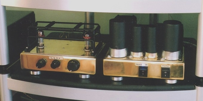
The "Nemo" line level preamp is on left side, and "Bunnerong"
power supply for line and phono stages
on right side. The names were chosen by the owner; I only made it
for him.
( There was an old coal fired power station in NSW at Bunnerong,
and a friend said that the preamp power
supply looked like that power station.
The Nemo is in its 3rd regeneration; it has been born again 3
times. It started with a simple schematic with
common cathode gain triode of 1/2 a 6CG7, resistance loaded, with
direct coupled cathode follower output.
Conrad Johnson used such a simple good sounding circuit way back
in about 1955, and very little improvements
have ever been made since then.
Initially, in 2000, a DACT attenuator was placed before the gain
tube, Siemens NOS 6CG7.
The Siemens µ is about 21, so gain became 18x, or 25dB, and a
little too high. The owner who initially bought
the amp sold it to its present owner in 2004. After some use, the
new owner regarded the high gain as a nuisance,
and felt that digital recordings tended to sound too "toppy",
harsh, on his Vienna Acoustic Mozart speakers.
So I then tried a µ-follower instead of the 1955 common cathode
gain stage and cathode follower.
The DACT remained ahead of the µ-follower, and a shunt NFB loop
added to reduce the high gain.
In the NFB loop, there was a switchable set of 3 x R&C series
networks to give a lowered and shelved HF response
for treble above 2kHz. These two new features sounded well. NOS
Siemens 6CG7 still tended to sound better than
Russian 6H30 which were tried.
The present form in 2011 is unchanged from 2005, and is described
in the schematic and notes below.
It sounds quite excellent with Siemens NOS 6CG7. Gain has been
reduced to only about 12dB with the shunt FB
which also allows the shelving networks to be included in the FB
loop. Overall, there are less HF losses in the signal
path and balance is more accurate.
Controls in the picture from left to right :- source select, HF
shelf levels, gain, mains on/off, phono amp on/off.
The line stage for Dec 2005....
The line stage amp only has one gain triode and one output cathode
follower, so one pair of 6CG7 is all that is
needed for both channels. V1 anode has its anode dc supplied
through the MJE350 constant current source which
was selected to keep the ac load on the tube high, and THD low.
The actual collector resistance is over many meg-ohms, and the
transistor acts passively, and does NOT inflict any
sonic signature. The triode's best sonic abilities are much aided
by the presence of the constant current source.
The input signal from the signal source selector feeds the Record
Out for those wanting direct connection for
recording purposes.
The input signal also is applied to the R1 resistance which is the
first R of the shunt NFB network formed by
R1 and R5.
It may be assumed that whatever source is selected, it will have a
low source resistance of say 600 ohms.
Where source resistance is higher, the amount of NFB applied
becomes higher, but few sources today have
Rout above 10k0.
The gain of the 6CG7 with the R5 270k load and the following DACT
100k switch is about 73k, so the triode
gain = 18x approximately.
This means if 0.1Vrms+ is applied to the grid, then Va = 1.8Vrms-,
and the phase of Va is opposite to grid signal.
So there is 1.9Vrms appearing across R5 270k, so current =
0.00703mA. It isn't much, only 7.03uA.
Grid input resistance is many meg-ohms. But there is 0.1Vrms
across R2 470k, so current = 0.213uA.
The R2 is used because it biases the grid to 0V if the source
signal is a "floating" signal that has no biasing
resistance, or the source is from the output side of a capacitance
with no grounding resistance.
An alternative is to use a 100k R between source switch pole and
0V. But doing it my way keeps the input
resistance at just above 47k.
Now the current in the R1 47 must be the total of the currents in
R5 and R2, ie, 7.23uA, so the voltage
required across the 47k = 0.3398Vrms, or say 0.34Vrms. The signal
input from the source must become
0.34 + 0.1Vrms = 0.44Vrms+. This means that with NFB you need
0.44Vrms+ input to produce output
= 1.8Vrms-, and signal voltage gain with NFB = 4.09x, or +12dB.
Hands up who didn't have a clue what the last two paragraphs were
about? Gee, I see a sea of hands.
It would matter if you were going to build this preamp, but other
wise does not matter. The point is that the
gain is only +12dB, or 4x, and that's enough, because a CD player
produces up to 1.4Vrms so the V1
anode signal maximum will reach 5.6Vrms.
The THD at this level without NFB would be approximately 0.2%, and
with the NFB it is reduced to
about 0.05%. Now most of the music level will be 1/20 of the
maximum level when THD will be also
1/20 of the maximum level, so expect to measure less than 0.01%
for 90% of whatever you like to listen to.
Meanwhile, the signal to noise ratio is just fabulous with the
source input raised in level before being applied
to the DACT volume switch.
Placing the volume attenuator BEFORE the gain triode means that
the source signal is reduced hugely, then
applied to the gain stage, and the noise of the tube gain stage is
at a much higher relative level to the signal,
and SNR is much worse than having the volume attenuator after the
gain stage, as I have it.
Now in addition to R5 = 270k, there is also R6, R7, R8 and C3, C4,
C5.
At LF below say 1kHz, these networks have very little effect, but
above 1kHz they begin to reduce the
total resistance between the grid and anode output. The networks
may be switched to give a shelved HF
response above 2 kHz so that nasty harsh recordings can be tamed a
little if required.
The output signal from the pole of the 100k log DACT volume switch
feeds the grid of V2 cathode follower
output buffer which has fixed bias. Such cathode followers have
utterly transparent sonics, and prevent HF
losses caused by long cables or high shunt capacitance of some
horrible solid state power amplifier.
The THD generated in V2 is reduced from about 0.4% without NFB at
5.6Vrms output to about 0.03%
by the "follower connection" which itself is application of about
16dB of local series voltage negative feedback.
At 1/20 of the max level, THD will be theoretically 0.0015%, so
nobody need worry that their triode amp is
the cause of the distortion that they may claim to be able to
hear.
There is some shunt regulation of the B+ voltage with a zener
string. When the phono amp is separately
switched on or off, there are no strange LF noises or cone wobbles
in speakers due to B+ rail variations.
I do not believe that Auricaps or many other brands of coupling
capacitors sound any better after having
recently trialled the above line stage where Wimas were in one
channel and Auricaps were in the other.
A customer friend and I used the same mono sound source through
each channel in turn with me trying to
trick my friend when I asked him to say which channel was better.
After about 6 changes of with 2 different
recordings, my friend could not pick any change or state any
preference which was better than chance, ie,
he liked the Wimas just as much as the Auricaps. I certainly could
not hear any difference let alone a "better"
sound with Auricaps.
However, my friend proceeded to have me replace all the Wimas in
his preamps and power amps with Auricaps.
I will always consider that my customers are always right, and
work as directed, but I don't myself think I
am missing out on better sound because I have not used Auricaps in
my own system.
Between 2006 when I wrote about the Wimas Vs Auricaps, and now,
2011, the Auricaps remain in most of
my friend's amps, except for one where he asked me to instal some
Russian made caps, probably polypropylene,
but army green colour suggesting they were spare parts for Russian
Army electronics.
My friend has another friend who talks to other friends and the
consensus of the "friend network" stretching
across the world and including mobs of typing bullshit artistes is
that Russian Brand X caps sound the best,
therefore must be installed, "or I won't listen to any music at
your place when I visit".
I've known audiophiles to change capacitors every 6 months until
nearly every possible available brand of
capacitor has been tried, each lot better than the last lot. But
not one A-B test was ever conducted.
Oh no, the irrational audio nutter can't stand logic or common
sense, and he cannot let himself ever be
cornered into a position when he must rely solely on his powers of
hearing to discern what sounds best.
I do not think many of the myths about special parts have much
validity. The circuit design and careful tube
choice are far more important to the sonic signature than brands
of the same type of cap, or different types
of hook up wire or solder or RCA sockets or speaker cabling.
The main reason to use better quality parts is reliability and
tolerance quality. For example a cheap Taiwan
made dual gain potentiometer costing $4.00 may have 15% difference
in L and R levels at the -20dB gain
setting but otherwise work perfectly - for 3 years, maybe, if used
a lot. Then it begins to make noises.
I won't use less than an Alps Black pot which is much more
expensive but they last 40 years.
Well, we might assume that, if the present production of Alps pots
is as good as it obviously was back in 1980.
There was good matching on their dual tracks at all levels, and
the carbon tracks didn't wear through easily
by countless rotations by the metal slider running around the
circular carbon track. But now its possible the
Alps "Black" 27mm square bodied sealed potentiometers are being
made in mainland China or some other
place and its difficult to say present production quality is the
same as its been in the past. The last lot I bought
from RS Components Australia measured well, and the price has come
down by nearly 50%, which suggests
RS is now sourcing Alps parts from a supplier who is far cheaper.
An Alps Black pot would be an easy thing
to copy.
The above Nemo has a DACT switched attenuator which is still
working well after many years, and the level
match is better than an Alps pot which usually within +/- 0.5dB
for L&R channels, and good enough.
I doubt there is any difference in the sound of either.
Tube choice for all the above preamps does have an effect on the
sound. This is true especially with the Rocket
which has no global FB for RIAA eq. Any tubed phono amp without
loop NFB such as the Rocket is more
prone to trouble from noisy tubes and microphony.
Unless tubes are properly tested for noise and microphony, not
just tested in a tube tester, then the sonic
outcome may be sub-optimal. I find the least noisy and least
microphonic tubes give the best performance
in terms of detail, dynamics, conveyed natural warmth, musicality,
tonal balance, sound stage, imaging and air.
Tubes that are old and tired, and possibly not so NOS as you may
think they were when you bought them
will perhaps sound less than optimal. It does no harm to have a
few different tubes to try, but one should
never change tubes each week because the pin grippers in tube
sockets may loose their spring pressure
and become loose, resulting in noise, intermittent connections and
a repair bill.
This is particularly so with some Chinese made brands of tube
sockets made in 1990s which do have nice
ceramic moldings, but have appalling metal alloy used for the pin
grippers. I worked on Quad-II-Forty
made in 1990s with extremely poor tube sockets. But I had a more
recently made Shanling amp here
which produced many clouds of smoke after 3 repair attempts my
someone else. Tube sockets were
very good, but just why there had been small fires on the printed
circuit board remained a mystery
because the customer was willing to pay for repairs.
NOS Mullard tubes must be getting now, in 2018. They are supposed
to have a "polite sound" with less
perceivable bass and treble while NOS Siemens are supposed to give
the best all round dynamics.
I find the NOS tubes made here in Australia 50+ years ago are as
good as anything made in Germany.
Under the NEMO :-

As everyone can see there isn't much room under the chassis with
Auricaps !
The messy tape with writing on it is just so I know where things
are when I have to service the amp
and normally the bottom cover plate completely covers over such
mess.
Everything is hand wired with three dimensional circuitry. The
wires from input sockets to source switch
are very fine Teflon insulated solid copper silver plated wires
which are fragile but supposed to be good
sounding. Solder has silver content, but just what a small % of
silver in solder does remains unquantified.
The ""Bunnerong"" power supply :-
This separate remote power supply is about 250mm long x 220m wide
x 170mm high.
It used to have a tube rectifier and tube regulator for a line
stage only when I sold it to fellow who ordered it with those
features in 2000. But that fellow sold it to another fellow ( for
$2,000 ) in 2004 and he contracted me to do the Rocket
phono amp stage. To enable the PSU to power both Nemo line amp and
Rocket phono amp, I suggested we increase
the power output capability and upgrade the supply by removing
tube rectifier and regulator and use only solid state
active devices.
The use of the silicon diodes etc allowed the PSU to function
without getting so hot. I found that heat with the PSU tubes
was enough to nearly cook the internally mounted electrolytic
capacitors. The plastic sheathing of a couple had begun to
shrink and tear from prolonged excessive heat. On hot days when
room temperature might be 32C, the under chassis
temperature might reach 70C.
With tubes gone there was room to place TWO power transformers,
one for B+ and a negative -16V rail for the phono
amp, and the other for the heating power needed for a total of 8
signal tubes. There was room for some high value
electrolytic capacitors. The power supply has functioned
flawlessly for years, and always runs cool.
I most certainly do not believe tubed power supplies improve the
sound.
T1 is a NOS spare part for 1950s Navy electronics, and well potted
and sealed. T2 is a generic 100VA tranny bought
from Jaycar electronics parts in Oz and it runs cool and quietly
enough after I potted it.
The large value power supply caps used for the dc heater supply
are what I have acquired from miscellaneous
purchases sales here and there but they are very well over rated
for their job.
C2, C3, C4 and R1, R2 form a CRCRC filter for the B+. Further RC
filtering is done within the chassis for the
line stage and phono stage which has a solid state follower
regulator, so there is NO NOISE from the rails or heaters
in this amplifier set up.
The dc heater supply does have a shunt regulator to steady the
heater voltage applied to the line stage.
This was prudent because the switching on and off of the phono amp
meant that the heater voltage varied too much to
the line stage unless it was regulated. This simple regulator
allows the removal of the line stage umbilical cable and the
regulator transistor, 2N3055 will pass all the heater power, about
12.6V x 0.6 amps, and without getting too hot.
Zener diodes alone are not as effective as the use of the zener
and trimmer diodes shown that are working with the
power transistor. My shunt regulator is very rugged, effective and
simple.
The heater supply to the phono stage has been made adjustable, see
R14 to R18 because there may be a time
when someone wants to change a tube type to something with more or
less heater current.
Back to
Preamps directory
To Rocket Phono Amp
Back to Index Page