SPEAKER MATCHING TRANSFORMERS. 2013

This page is about speaker matching transformers.
Fig 1 to 13 show details of transformers and all is explained.
There is sometimes a good reason to use a transformer between an amplifier and speaker
to improve the sound quality and improve all measured parameters in terms of power ceiling range, distortion,
bandwidth, and damping factor.
The transformer is called a Speaker Matching Transformer, or SMT, and is usually a black box connected by
short cables from amplifier and to which existing speaker cables may be plugged in.

In most cases, the transformer effectively converts a low impedance speaker to a higher impedance.

A typical speaker may have a nominal impedance Z of "4 ohms" printed on the label. Impedance in ohms is
the resistance which varies with frequency because the resistance is connected to inductance and capacitance
to form a complex network of L, C and R. The speaker voice coils have wire resistance and inductance,
and the crossover filters have L, C and R parts. At the lowest frequencies of bass or midrange drivers the
box interacts with drivers and in a manner equal to having some LCR network, even though no real L or C
are present for the behavior in the box. Resonance of all dynamic drivers at their lowest F resemble a high Q
parallel tuned circuit.

So a typical 4r0 speaker may have varying Z between say 3r0 and 6r0 for most of the F band plus a couple
of peaks up to 40r at between 20Hz and 70Hz.
Loudspeakers are designed to make a constant SPL at all frequencies where the input Vac remains constant
for all frequencies. So where you see the Z is say 30r0 at say 50Hz for a 4r0 speaker, the same 2Vrms for
4r0 or 30r makes the same SPL, even though power varies between 0.13W for 30r0 and 1W for 2r0.
Amplifiers are made to work with a range of speaker loads between 3r0 and 30r0, and good load-matching
brings best amplifier performance.

A 4r0 speaker should not be used with an amp designed to work with 8r0 or 16r0 or higher because the amp
may overheat, THD may be too high, max Po could be too low, and music may sound unwell.
The Ohm is a unit of resistance, and R = V / I the where 1V produces 1Amp current, R = 1V / 1A = 1 ohm, or r.
R defies common sense because the less ohms there are, the harder it is for an amp to produce sound.
Common sense dos not apply to R as it does to bricks on a truck. The more bricks on the truck, the more difficult
becomes to drive up a hill. No matter what I say, ppl don't remember MORE Ohms = easier for amp, no smoke,
LESS ohms = harder for amp, and amp smokes.

The lower the speaker ohms, the higher the current needed to produce the same power output and sound level.
If a 4r0 speaker sensitivity is rated for SPL = 88dB / W at 1M, the amp makes 2Vrms and current 0.5Arms.
Power Po is calculated P = Vrms x Irms, or Vrms squared / R, or Irms squared x R.
If Po = 10W to 4r0, 10W = Vrms squared / 4r0 so Vrms = sq.rt ( 10W x 4r0 ) = sq.rt 40 = 6.3Vrms.
Iac = 6,3Vrms / 4r0 = 1.58Arms.

The 4r0 speaker Z may vary above and below 4r0 between say 2r5 and 30r and all are designed to make the
same SPL for the same applied Vac for all F between say 30Hz to 20kHz. So average speaker sensitivity may
be 88dB/W/M but it varies between 85dB to 95dB because the power needed for 88dB varies with frequency.
Where speaker Z is lower than nominal, say 2r5, and where speaker sensitivity is low, it may be due to crossover
filter action, but the amp must be able to make higher current than where Z = 5r0, but be able to provide the
same Vac for 2r5 or 5r0.

All this may bamboozle many ppl but get the best music, vacuum tubes need to have just the right transformers
to work with speaker loads. Transformers are like gearboxes in a car where the engine is happy making
20kW at say 2,500rpm along a flat road at 60kph. The ratio of engine rpm : wheel rpm may be 2 : 1.
But up a steep hill the power needed for 60kph may be 40kW, and engine is not happy, so you need to slow
down to 30kph where power needed is 20kW, and change gear so that engine rpm : wheel rpm is 4 : 1, so
engine happily turns at 2,500rpm and makes 20kW, but speed is lower uphill. Vacuum tubes are like the car
engine and need to have a transformer which converts high Vac at low current to become low Vac at high
current for speakers.

2 tubes making 20W with 316Vrms applied to 5,000r load of a primary winding on OPT can be converted
to 20W with 12.6Vrms at secondary applied to 8r0. if the same 20W is wanted for 4r0, secondary turns
must change to give 8.9Vrms and for 16r0, change to 17.8Vrms.

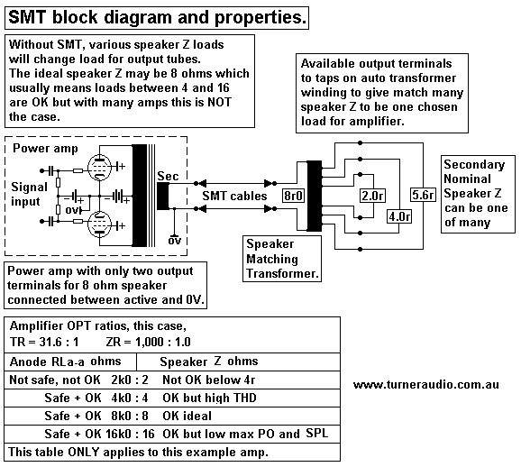
Fig 1.
SMT-block-diagram-properties.GIF
The above shows a typical set up where someone may wish to ensure that a speaker with a nominal Z that is
either above or below the ideal load value for the amp can be converted into an impedance that is ideal for
the amplifier, and hopefully the resulting music replay will include less amplifier distortion, will not cause tubes
to overheat, and will give better damping factor, and all of this without winding losses exceeding 5%, and
without reducing the bandwidth of signal applied to the speaker.

Suppose you consider one channel of my 5050 amp.

For this amp, 8r0 is a very nice load for each channel. In fact, all speaker loads between 4r0 and 16r0
are very well tolerated, and one would not really need a SMT at all.

Suppose the 5050 had only one one pair of output terminals labelled "8 ohms".
Suppose I wanted to power a 2r0 speaker, or 2 x 4r0 speakers in parallel.
Then the SMT would be a good idea, because 2r0 is a dangerous and bad sounding load to connect,
especially if it has low sensitivity needing high power to generate a wanted sound level.

Many people will purchase the most powerful amplifier they can afford, and then buy the most expensive
speakers without worrying about sensitivity, impedance, load matching, or power, or anything else at all,
except how to get it home and hook it all up. This is what many audiophiles tend to do, and they have almost
zero idea just what an ohm is. It could be what you hear at a yoga class. Impedance could be impudence, but
no, impedance implies that something impedes something happening, but just WTF is it?
Anyway, a good salesman knows how to jargon about technical stuff in just the right way to have the buyer
think that everything will be fine when things are hooked up at home.

Well, 95% of the world's people have very little idea how anything really works. Shish ! trying to understand
their wife is easier than stuff about electronics. "Hi-Fi" 3 in 1 sound systems with 2 speakers meant for the system
took all the guesswork out of buying sound gear. But 5% of music listeners expect more hi-fi than is available
from bargain 3 in 1 systems costing under $500. Some are extremely fussy about sensitivity, impedance,
load matching, and power because they know that if they understand these issues and apply the knowledge
they don't have to spend so much as those who buy far more expensive amps and speakers, but who do not
get music any better.

Fig 2.
speaker-sensitivity-power-needed.GIF
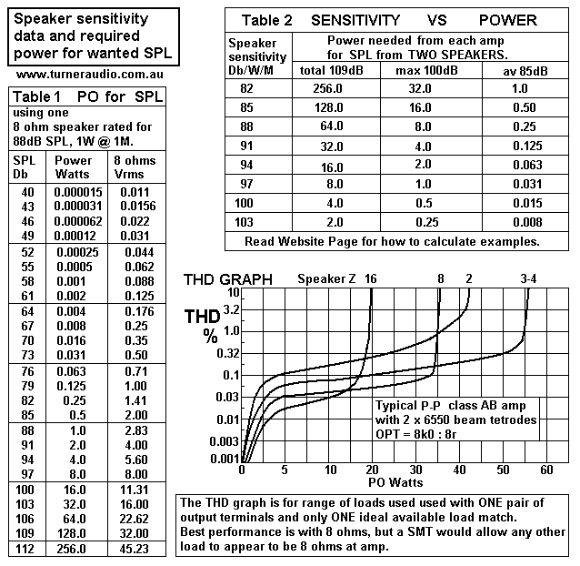
Here is a nice tricky little picky if ever there was one!!

Before 1955, just what ppl needed in terms of amp power and sound pressure levels SPL was well investigated.
On page 623, of 1955 Radiotron Designer's Handbook, 4th Ed, it said the "preferred maximum sound levels"
for men and women was 78dB for symphonic music, which assumes the average reading from a sound level
meter hovered around 78dB. We might assume instantaneous peak SPL could vary +/- 30dB. 
Maximum levels for musicians was 88dB, and highest levels for male "programme engineers" was 90dB.
Today, any tests may show men and women may prefer slightly higher levels especially since higher levels of bass
exist in much pop music and film sound tracks et all. Older people like lower SPL than younger people, unless they
have gone deaf.
My tests using simple SPL meters in lounge-rooms reveals that 85dB is a maximum average for most people,
for most music. Classical orchestral music may linger at average levels much lower than 85dB, but also soar
briefly to 100dB. Much pop music will sit between 85dB and 91dB, with very little change to level because of
compression and repetitive drum and bass levels and because of young people's preferences for continual
Boom-Chikka-Boom & rap garbage.

For most serious hi-fi listeners, their speakers and amp must be able to make SPL = 100dB at least.
Their average level may be say 85dB.

Suppose you have X-Brand speakers rated for 88dB / W / M, ie, with 1.0W they make SPL = 88dB at a
microphone 1M in front of speaker in an anechoic chamber and for most sine wave F between 20Hz and 20kHz.
Inside a nicely carpeted lounge room with lounge chairs and absorbent furnishings and window drapes, the 1.0W
may produce 88dB 3 meters, allowing for reflected sound. Music energy is a mix of very many frequencies in
dynamically varying levels and one should find the quantities mentioned so far will be about correct.

Stereo Hi-Fi systems may have two speakers which together make 88dB, so each makes 85dB with 0.5W each.
For each 3dB change of SPL, power has doubled or halved and for each 10dB SPL change, power has changed
by 1/10 or 10.
Because average room SPL may need not exceed 85dB, each speaker produces 82dB, and table 1 in Fig 2
shows each amp Po = 0.25W for total 85dB.
For 95dB, each amp makes 2.5W, and for 105dB each amp makes 25dB, and 50W would make 108dB.
Most recorded music has had its dynamic range limited or compressed and the 85dB to 106dB is enough.
You go to a concert in an art gallery that is reverberant and find that a saxaphone and trumpet player and drummer
3M away will seem much louder than anything you hear from your 2 x 50W amps at home, yet it seems natural and
OK and has freshness and dynamics because nothing is used to limit the sound levels except your own ears which
have reducing dynamic range as you get older. Most ppl will never ever want to have their Hi-Fi system go
as loud as some real concerts where you are close to what are naturally loud instruments. If you were to sit among
the brass section of a large orchestra you would soon beg for ear plugs.

Therefore, the use of 2 x 6550, KT88, KT90, KT120 in each amp channel usually gives "enough" power.

But whether it really is enough can depend on impedances, not just sensitivity. The more sensitive the speakers,
the less power you need. Many are now made with rating 88dB / W / M and many are 4r0, with minimum
Z to 2r5.
Fig 3.
graph-po-vs-rl-2x6550-pp+pse-29-4-13.GIF
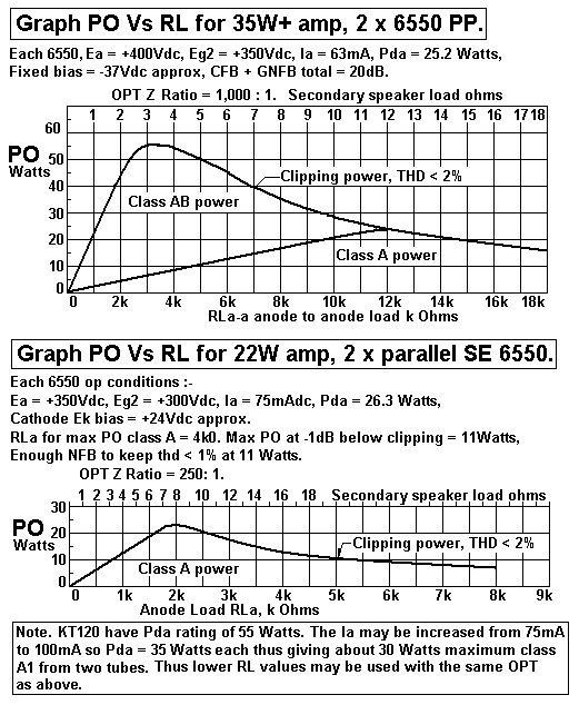
The two graphs show what power may be expected from 2 x 6550 ( or KT88 etc ).
The graphs are prepared from tests carried out on an amp with given operating conditions and with OPT
matching giving 8k0 : 8r0 load matching setting.

The PP amp can give up to 55W with a 3r0 load, but that doesn't mean you must use a 3r0 speaker load.
With loads less than 4r0, THD becomes high because class A working portion is a low % of total possible
class AB power, and tubes are pushed to work in a more non linear manner. The amount of NFB becomes
lower when load is reduced, and Damping Factor is lower.
With 8r0, you get 35W max, and perceived SPL maximum at clipping is only -2dB below level for 55W
not often perceived. The sound with 8r0 speaker will be better than with 3r0 speaker.

The variations with THD when using different loads can be seen in THD graph in Fig 2. The THD levels have
been drawn on a logarithmic scale, so you need to read the variations carefully.
Basically, the higher the speaker ohms, the lower the THD, IMD and all other distortion.

But if the load is 16r0, the available max Po is only 18W. But it is all pure class A Po and THD and IMD has
reached a level will little more reduction if load is made even higher. With 16r0, and if clipping does not occur
with most music, the sound should be as good as it ever could be, providing the speakers also have low THD
and IMD.

The 5050 makes maximum Po with load less
than 1/2 the ideal nominal speaker Z, ie, max Po occurs with 3r0
where output terminals are labelled "8 ohms". Many commercially made amps are set up so where load = 8r0,
and labelled outlet says "8 ohms", the Po = 55W and tubes are forced to struggle so THD, IMD is high and
damping factor low. But the manufacturers must be able to offer higher power than their competition, because
dopey customers shop for power, not for real Hi-Fi, and men like to think they have bought something bigger
and better than the man next door.

If an amp makes its maximum Po with 8r0 speaker, using a 4r0 speaker might damage the amp. Never ever buy
any tube amp which does not have an output terminal labelled "4 ohms". At least your 8r0 speaker might sound
best when the 4r0 outlet is used.

Many amps may have output terminals labelled "4 ohms" and "8 ohms", but what works best is 8r0 or 16r0
respectively. To overcome such a problem, the Speaker Matching Transformer, SMT, can be used to make
a 4r0 speaker become an amp load of 8r0 with 1.4 : 1.0 turn ratio, or become 16r0 with 2.0 : 1.0 turn ratio.

An SE amp with 2 parallel SE 6550 has a very different OPT, and the tubes always work in class A.
So you might expect 2 parallel SE 6550 to make about 23W maximum and that is for only one speaker Z value
and for all Z above and below the Po will be less. But it will always be class A Po only, and often it sounds better
than a PP amp capable of 55W in class AB.
A typical SE amp might be set up to make 23W for 6r0. This will work well for an 8r0 speaker with dips to 6r0,
but with 4r0 and dips to 3r0, the action is tolerated, but max Po may be 16W.

Load matching is more critical for SE amps than for any PP amp of the same Po, because SE amps cannot
generate class AB Po that can be up to 3 times the maximum pure class A Po maximum.
Therefore all SE amps should have OPT which have links to select loads of 3r0, 6r0, 12r0. For those which
have only one output labelled "8 ohms", having an SMT is a very good idea to make 4r0 or 16r0 become
8r0 load at amp.

Some old amps are much loved, such as Quad-II. These have a pair of KT66 with OPT links arranged to
give Z ratio 4k0 : 9r0 or 16r0. But many ppl try to use 4r0 speakers with OPT links set for 9r0.
The load RLa-a for tubes becomes only 2k0, giving only 3W of initial class A with another 10W of not
so good class AB.
But best Hi-Fi is achieved with anode RLa-a = 8k0, and there is nearly 18W of pure class A but the load
connected to OPT should be 16r0 with 9r0 links. With OPT linked for 16r0, best speaker load = 32r0
The 16r0 links give lowest winding losses and best hi-fi so use of a good SMT which can make a 4r0
speaker become 32r is needed, ie, Z ratio = 32r : 4r0 = 8 : 1 so turn ratio = 2.83 : 1.0.

OTL amps.
Many OTL amps are claimed to be able to power 4r0 speakers. The only really good OTL amps which can
so this brilliantly will have 3 x N-type and 3 x P-type power mosfets. But any amp with say 8 x 6AS7 or 4 x
6C33c will always be struggling to power 4r0, with tubes likely to overheat and die soon.
My experience tells me just about all OTL amps work better with a much higher load value, maybe 16r, 32r,
64r, ir 128r !
In many OTL amps, use of 16r0 speaker instead of 4r0 will much increase available maximum Po, increase
damping factor by 4, and reduce THD/IMD by 1/4. So why? 
Fig 4.
6AS7G-classA-Ab-loadlines.GIF
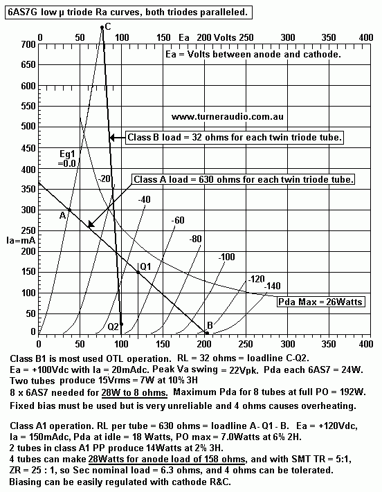
Fig 4 shows Ra curves and class A and B load lines for one 6AS7 with both its triodes paralleled.
Loadline A-Q1-B for class A Po with RLa = 630r shows loadline intersects Ra curves linearly, and gives 7W
of pure class A1 with total Pda at idle = 18W. Using 2 x 6AS7 in class A1 PP would give 14W and 2H is
cancelled leaving a probable 1% 3H with RLa-a = 1,260r. What a fine result, to be sure ! But there MUST
be a normal PP OPT with Z ratio 1,260r : 4r0, 8r0, 16r0.
If the pair of 6AS7 are in series, or in Circlotron mode, OPT is still needed for class A and is 315r : 4r0, 8r0, 16r0.
4 x 6AS7 could give 28W class A to 157r : 4r0, 8r0, 16r0.
There may not be many SMT able to give maximum Z ratio of 40 : 1, ie, TR = 6.3 : 1.0.
But while each 6AS7 works with class A anode load of 1,260r, the peak Ia = 300mA, and the tube should last
a long time.

But with the same 2 x 6AS7 in series, set up to idle at 2.5W each, and with no OPT and load = 32r, loadline
C-Q gives 22Vpk swing on 32r, Po = 7.5W, and it is virtually pure class B with very high THD and atrocious
damping factor and about 40dB of GNFB is needed to correct the non-linearity. Max Pda of each 6AS7 due to
Vac operation can be 24W each. But 8 x 6AS7 would give 30W for 8r0 load.
Peak Ia for each 6AS7 is over 700mA, and I have seen too many samples of 6AS7 being unwilling to pass
more than 300mApk. They begin to arc internally with excessive Ia. If the load was 16r0 or lower for one
paralleled 6AS7, peak Ia can go alarmingly high without any more useful Po.

For 8 x 6AS7, with 4 pairs in series, with each 6AS7 having Ra 140r, total Ra = 140 / 8 = 18r approx.
If the load = 8r0, DF = 0.44, very poor, because DF should be 10. But with Technics driver or Circlotron,
Rout would be lower at 10r0. If the load = 8r0, DF is still poor at < 1.0, and 20dB GNFB must be used to get
DF to 10 and THD under 1% at 30W.

Many OTL need 40dB of GNFB to force the circuit to measure acceptably. This is possible because there is
no OPT with its inherent phase shift at LF and HF which is included in the FB loop. An SMT does not need
to be included in any NFB loop. The SMT can reduce the amount of GNFB needed to 12dB, and at least
one gain stage may be omitted. Output power maximum can be doubled, with much more class A1 Po.

I think use of 6AS7 in virtual class B1 is The Worst way to use tubes, especially with a very low value of RL
that is like connecting a short circuit. An SMT will allow better operation for an amp set up for B1. With SMT
the idle Iadc can be increased to get an acceptable amount of initial class A and class AB Po.

High power tube amps or SS amps may be more load tolerant because people use the same power for the
same sound level regardless of the power output. A 20W amp needs good load matching but a 200W amp
may not.

Nearly all tube amps capable of 70W+ AB may produce 0.4 % THD at 70W or just before the wave form
begins to clip. So if speaker is 8r0, Vo = 23.6Vrms. But average listening levels may be at 0.5W which is 2.0Vrms,
and THD is approximately proportional to Vo, so THD at 0.5W = 0.4% x ( 2 / 23.6 ) = 0.034%, and low enough.
If a 2r0 speaker is used, and Vo adjusted for 1.0Vrms to make 0.5W, what would THD be?
A 2r0 load may allow 35W max x 1% at 8.3Vrms, so at 1.0Vrms expect THD = 0.12%, nearly 4 times as much
as having 1.0W with 8r0, but most ppl would not find the sound to be bad.
With a 20W amp giving only 10W for 2r0, and 1% THD, Vo = 4.5Vrms, and at 0.5W the Vo = 1Vrms, so THD
= 0.22%. Many ppl would find this OK but they may also find the amp has poor dynamics. 
20W for 8r0 is 12.6Vrms and THD may be 0.4%, and at 2Vrms for 0.5W, THD = 0.063%, a much better result.

With amplifier power = 50W for needed for 106dB SPL with speakers 88dB/W/M :-
1. Provide the amp with a load value it prefers.
2. The speaker ohms between 50Hz and 1kHz should always be higher than what is labelled on the
amp terminals.
3. Use SMT to transform low speaker Z to higher load for amp which already has OPT for 8r0 or 16r0 speaker.
4. Impedance matches available with SMT should be approximately as in the table :-
Table 1.
Nominal
Amp load
Ohms, r
SMT Input
= 200 turns.
Load Ohms, r
Sec = 141 turns.
Load  Ohms, r
Sec = 100 turns.
Load Ohms, r
Sec = 70 turns.
Load Ohms, r
16r0
32r0 16r0 8r0 4r0
8r0
16r0 8r0
4r0 2r0

It is difficult to design a single 50W audio F transformer which can work with primary load variations between
8r0 and 64r.
It is better I give you TWO designs, SMT-1 to work with OTL amps and SMT-2 to work with amps which have
an OPT, or they are solid state and more class A with less class AB is wanted.

SMT-1 will be for tube OTL amp and allows 50W for 64r0 : 4r0, 8r0 and 16r0, with input 128r or 32r. 

SMT-2 will be for amp with OPT or is SS amp and allows for 50W for 16r0 load where labelled output load
terminals are between 8r0 and 16r0, and load wanted is 16r0 to 32r0 with any speaker between 1r0 and 8r0.

Design of 50W SMT-1. 64r : 2r0, 4r0, 8r0 and 16r0.

1. Use GOSS E+I lams, wasteless pattern. ISOLATION transformer with primary and secondary.

2. From PP OPT calcs 2, Afe = 300 x sq.rt Po = 300 x sq.rt 50 = 2,121sq.mm.

3. Choose core size with T x S = 2,121sq.mm.
Try T51mm, then S = 41.6mm. Use molded plastic bobbin T51mm x S51mm,  reduce S to 41mm.

4. Confirm core dimensions T51mm, S41mm, L75mm, H 25mm. Afe = 51 x 41 = 2,091sq.mm.

5. Calculate theoretical primary turns Np = 22.6 x Vac x 10,000 / ( Afe x F x Bac max ).
Vac = 56Vrms, max Bac = 1.5Tesla at 14Hz, Np = 22.6 x 56 x 10,000 / ( 2,091 x 14 x 1.5 ) = 288turns.

6. Calculate P o/a dia wire = sq.rt ( 0.28 x L x H / Np ) = sq.rt ( 0.28 x 75 x 25 / 288 ) = 1.350mm
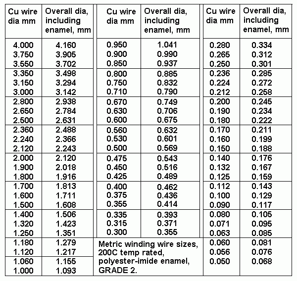
Table 2. Wire sizes.
table-wire-sizes.gif
7. From table for wire sizes, use nearest oa size = 1.351mm oa = 1.25mm Cu dia.

8. Calculate primary turns per layer Ptpl, number of primary layers, revised Np.
Bobbin winding width Bww = 75mm - 4mm for 2 cheeks = 71mm. PTL = 0.97 x Bww / oa dia
= 0.97 x 71mm / 1.351mm = 50.97, say 51tpl. 
Primary layers = th Np / Ptpl = 288 / 51tpl = 5.65layers. Use 6.0 layers.
Revised Np = 6 x 52 = 312turns.

9. Calculate RwP = Np x Turn Length / ( 44,000 x Cu dia squared ).
TL = pye x H + 2 x ( T + S ) = 282mm.
RwP = 312t x 282mm / ( 44,000 x 1.25mm x 1.25mm ) = 1.28r.

10. Calculate Primary winding loss % = 100% x RwP / ( RwP + Pri load ) = 100% x 1.28r / ( 1.28r + 64r )
= 1.96% = OK where wanted max Pri loss < 2.5%.
For Primary = 32r, P loss = 100% x 1.28r / 33.28r = 3.9%

11. Calculate expected Lp = 1.26 x Np squared x Afe x µ / ( 1,000,000,000 x ML. )
E+I GOSS core µ will vary between about 1,000 for low Bac for most listening levels and up to say 5,000
for high Bac at say 20Hz.
For lowest levels, Lp = 1.26 x 0.312 x 0.312 x 2,091 x 1,000 / ( 1,000 x 280 ) = 0.92H.
For highest levels, µ = 5,000, Lp = 4.6H

12. Calculate minimum Lp required where XL = RL at 14Hz. Lp = 64r / ( 6.28 x 14Hz ) = 0.72H
Minimum Lp with µ = 1,000 = 0.92H = OK.

13. Calculate height of bobbin available for secondary.
Total maximum allowed height for all bobbin content = 0.8 x H = 0.8 x 25mm = 20mm.
Primary height = 6 x 1.351mm = 8.106mm.
Total maximum height of secondary plus insulation = 20mm - 8.106mm = 11.894mm.
Allow Sec winding height same as Pri = 8.106mm. Insulation height = 11.894mm - 8.106mm = 3.78mm.
Note. Insulation may be say 10 x 0.20mm Nomex = 2.0mm, Sec winding height could be 9.894mm.

14. Select interleaving section sequence pattern for wide bandwidth = 3P + 4S = S-pp-S-pp-S-pp-S.
Confirm section layers. Primary has 2 layers of wire in each of 3 sections, Secondary has 1 layer of wire in each
of 4 sections.

15. Calculate maximum possible secondary wire oa dia = Sec wire height / No layers = 9.894mm / 4 = 2.473mm.
Select a wire size = 2.366mm oa for 2.24mm Cu dia.

16. Calculate possible Sec tpl = Bww / oa Sec dia = 71mm / 2.37mm = 30tpl.

17. Calculate possible P : S TR and ZR and Sec loads for 312 Primary turns : 1 possible layer 30t secondary.
TR = 312 / 30 = 10.4. ZR = 108.16 :1. For Pri RL = 64r, Sec = 64 / 108.16 = 0.592r.
For 4 x 30t sec in series, Ns = 120t, Sec load could be 9.44r.
The range of sec loads is too low. Wanted range of Sec loads = 1r0 to 16r0.

18. Calculate Sec turns for Sec load = 1r0. ZR = 64r / 1r0 = 64 :1. TR = 8.0 : 1.0. Ns = 312t / 8.0 = 39turns.
Sec load for 39t = 1.0r, and for 4 x 39t in series 156t = 16r0.

19. Are Sec turns in step 18 divisible exactly by 12? Yes, 156t / 12 = 13.00.

20. Calculate Sec wire size = 71mm / 39tpl = 1.820mm oa dia, choose 1.813mm oa dia for 1.70mm Cu dia.
Therefore 4 layers of Sec may have one layer divided to make 3 equal turn windings to get larger number of
useful load matches :-
Table 3. Useful load matches.
Pri = 6 x 52t
Np 312t
4 // 39t
Ns = 39t
3 // ( 39t+13t )
Ns = 52t
2 // ( 39t+39t )
Ns = 78t
3 x 39t series
Ns 117t
4 x 39t series
Ns = 156t
RwP
loss%
RwS
loss%
128r
2.00r
3.55r
8.00r
18.00r
32.00r
0.9%
1.2%
64r 1.00r 1.78r
4.00r
9.00r
16.00r
2.0%
2.4%
32r
0.50r
0.89r
2.00r
4.50r 8.00r
3.9%
4.6%

21. Calculate Sec winding loss %.
Maximum loss is for 3 x 39t in series. Rw for 39t = 39t x 282mm / ( 44,000 x 1.7mm x 1.70mm ) = 0.087r.
Windings aranged 39t + ( 2 // 39t ) + 39t = 117t, RwS = 0.087r + 0.043r + 0.087r = 0.217r.
Where Sec = 9r0, RwS loss % = 100% x 0.217r / ( 0.217r + 9.00r ) = 2.35%.
Sec = 4.50r, RwS % = 4.60%, and Sec = 18r0, RwS % = 1.20%.

22. Calculate maximum total P + S losses for 32r : 4r5 = 3.9% + 4.6% = 8.5% < 10% = OK.
If amplifier Rout = 3r2, calculate output resistance for Sec load for 32r : 4r5 use.
Rout at sec = 0.45r, SMT Rw total at sec = 8.5% x 4r5 = 0.38r, total Rout = 0.83r.
Damping Factor = 4r5 / 0.83 = 5.4.
If SMT used for 64r : 9r0, and amp Rout = 6r4, at Sec Rout = 0.9r, and SMT Rw = 4.4% x 9r0 = 0.4r.
Total Rout = 0.9r + 0.4r = 1.3r, DF = 9r0 / 1.3r = 6.9.
Better DF is achieved with use of enough NFB at amp to lower amp Rout. 

23. Calculate LL = 0.417 x Np squared x TL x [ ( 2 x n x c ) + a ] / ( 1,000,000,000 x n squared x b )
where LL = leakage inductance in Henry, 0.417 is a constant for all equations to work, Np = primary
turns, TL = average turn length around bobbin, 2 is a constant because there is an area at each end
of a layer where leakage occurs, n = number of dielectric gaps, ie, the concentric gaps between layers
of P and S windings. c = the dielectric gap, ie, the distance between the copper wire surfaces of P and
S windings, a = height of the finished winding in the bobbin, b = the traverse width of the winding
across the bobbin. Distances are all in mm!

SMT-1, LL = 0.417 x 0.312 squared x 282mm [ ( 2 x 6 x 0.25mm ) + 17mm ] / ( 1,000 x 6 x 6 x 71mm )
= 0.0895mH = leakage inductance looking into primary.
Assume amp Rout = 6r4, SMT primary input = 64r, then -3dB response pole F is where XLL = 64r,
F = 64r / ( 6.28 x 0.0000895H ) = 114kHz, > 50kHz = OK.
Where SMT primary load = 32r, -3dB pole = 57kHz, OK.

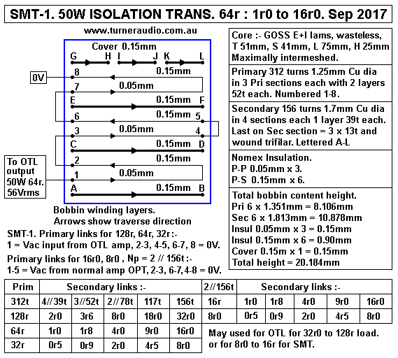
24. SMT-1. All details of windings and bobbin layers.
Fig 5. SMT-1 for Pri 128r to 8r0, Sec 0r5 to 32r0.
SMT-1-50W-Isolation-128r-32r-0r5-32r0-Sep-2017.GIF
SMT-1 with Np = 312 turns was calculated for load ratios = Pri 64r : 1r0 to 16r0 Secs.
But it can be used for 128r : 2r0 to 32r0, and for 32r0 : 0r5 : 8r0.

It can also have Np = 156 turns where each 1/2 of primary is paralleled.
This gives load ratios 16r0 : 1r0 to 16r0, and for 32r0 : 0r5 to 8r0.

The frequency response and winding losses will be the same for Primary = 312 turns or 156t.
For Np = 312t :-
128r primary load, 80Vrms = 50W, Fsat = 18Hz.
64r0 primary load, 56.5Vrms = 50W, Fsat = 12.9Hz.
32r0 primary load, 56.5Vrms = 100W, Fsat = 12.9Hz.

Where Np = 156t :-
16r0 primary load, 28.3Vrms = 50W, Fsat = 12.9Hz.
8r0 primary load, 28.3 Vrms = 100W, Fsat = 12.9Hz.  

If you don't mind Fsat occurring at a higher F, then higher Vac may be used for higher power handling.

Some DIYers find they have a pile of old power transformers from which they think they might make
something useful such as a SMT. The most common large old E&I lamination size will be "wasteless pattern"
with tongue = 38mm and window size of 19mm x 57mm. The iron quality of old PTs is usually quite horrible
which will ensure iron caused distortion is too high, and the µ is low so there will be low inductance.

For the best SMT or for any OPT handling audio F signals, you need GOSS E+I laminations or C-cores.
To make anything like SMT-1, you need to BUY core material, and that upsets DIYers who hate paying for
anything. SMT-1 core will be about 5Kg, so expect to pay $25 per Kg. Only new Grade 2 winding wire
should be used and that won't be cheap.

The distortion caused by iron cores in audio circuits is due to change of inductance during each wave cycle
so for Vac near the zero crossing points of a sine wave, L is low but L may be highest at the highest design Vac.
3H is the main harmonic produced by the non linear iron cored reactance and analysis would reveal that an
equivalent network of R and diodes could be made to replicate the change of inductance reactance and its
average but varying impedance at say above 30Hz is well any proposed load value.

If any iron cored transformer is driven by a current source, ie, high Z Vac source, the distortion is highest
when no load is used. The distortion becomes lower when a load is connected but where the Vac source
becomes very low, this shunts the apparent non linear network in the iron so distortion is minimized.

So with SMT-1, when set for 64r0 : 4r0 operation, the iron distortion is highest when an amp has high Rout
above 100r. But if the amp is an OTL and there is enough GNFB, the amp Rout can become say 10r0,
and this shunts the primary inductance and its non linear network with average Z above the primary L.
if the SMT has load ratio 64r : 4r0, then ZR = 16 : 1.0 so 10r0 for amp Rout becomes 0.62r at the
SMT secondary.

THERE ARE EXAMPLES of speaker matching trannies which use an auto transformer with ONE winding to
give input load = 8r0 and with taps for speaker loads of 4r0, 2r0, 1r0, 0r5. One type I have tested is made by
Paul Speltz at http://www.zeroimpedance.com
It is a toroidal type with excellent bandwidth to over 500kHz. Two audiophiles here in Canberra bought them
and were well pleased. One bought the simple un-boxed version which I was asked to enclose in a box.
I made a wooden box and mounted the tranny inside and surrounded with compacted dry sand. I used plastic
foam between lid and sand to keep some active pressure on the contents. Transformer was siliconed to bottom
of box so movement creep is not possible.

I found toroidal windings were very messily wound but the measurements were very good. Toroidal transformers
are difficult to without a toroidal winding machine. I once re-wound a couple of power transformers by hand
by making a shuttle from 20mm dia wooden dowel and length about the same as 1 turn length for the 500VA
core. Wire was first wound onto shuttle then unwound onto core by passing shuttle through the core hole and
pulling wire tight, and winding speed is extremely slow so one transformer too 2 days to wind.
 
A DIYer will need to think a lot about where all the turns lay and how he winds a toroid for wide bandwidth.
Trying to make an autotransformer which has low winding losses and good HF where TR exceeds 3:1 can be
difficult. With TR = 3 : 1, there may be 300t for one winding, and a tap at 100t for the shared winding. The
shared winding should be 2 x 100t windings paralleled and all 200t for shared winding wound over top of
first 200t.

Woven polyester tape should be used for insulation between layers because it allows easy varnish impregnation
when wound toroid is soaked in a can of varnish.

There is much to be learnt about toroidal transformers, and I am no expert because I found toroidal cores were
only ever useful for audion F where no Idc current flow was possible, which is the case for all PT and some OPT
which are coupled to tubes or mosfets with C. I didn't like any of the toroidal OPTs and PTs I found in equipment
I was asked to repair or re-engineer.

So my simple advice about DIY toroidals is "DON'T DO IT" and use E+I or C-cores and wound bobbins.

Any single winding transformer with taps, ie, auto-transformer wound on a bobbin for E+I or C-cores will work
well for 50Hz without worrying about leakage inductance. I have a 200VA PT on bench with many 20Vac windings
in series and for 240Vac mains inpu, all wound on double-O C-corest. I use a high current rated rotary switch to
obtain variable Vac to suit a soldering iron or anything else where I may need to supply with low Vac at 50Hz,
so my switched PT functions as a Variac.

But with this autotransformer set for 240Vac input and 20Vac output, its F response over 50Hz is very limited
because leakage inductance is very high between one 20Vac portion of winding and all the turns in series for
240Vac. For 240Vac input and for 200W input, the input load = 288r, and input Iac = 0.83A. If the shared load
winding is for 20Vac and Po = 200W, the output load = 2r0, and load Iac = 10A. The current in shared winding
= output load current - input load current = 10A - 0.83A - 9.17A. This Iac would soon overheat the 20Vac
winding so I would never use a 2r0 load and would have minimum load for 20Vac of 10r, for 2A max Iac.
This means output Po = 40W, and input load = 1.440r for input 240Vac.

If I raised the F for the 240V : 20V autoT I would find the response would get F2 cut off well below 1kHz.
If I wanted to increase the response I'd have to add maybe 4 more 20Vac windings and evenly interleave them
with all other windings  as I show in many of my OPT bobbin layer diagrams. All 20V windings are paralleled,
and can be in series with the remaining windings for 240V input. So the rules for good HF response from
autoT are the same as for isolation transformers.

Consider you have 8 layers of wire on a given bobbin for one winding, occupying a window 19mm x 57mm.
Suppose you devote the bottom 2 layers for a shared secondary for 2r0. The TR = 4 : 1, so ZR = 16 : 1
so input load = 16r0. You may find than HF bandwidth does not reach 8kHz. To increase the bandwidth, the
2 layers used for 2r0 could be moved up from bottom to be the 3rd and 6th layer wound on. The series
with 6 winding in series with 2 layers also in series is kept the same, and bandwidth will be increased. But you
will find HF cut off still too low. The cure is to add 2 more winding layers for a total of 10 layers. There can be
10 layers numbered 1 to 10, with layer numbers 2, 4, 7, 9 devoted to the shared load winding and layers
1, 3, 5, 6, 7, 8, 10 interleaved up the height of bobbin. The F2 cut off will be a lot higher than using just 2 bottom
layers of a total of 8 layers. arranged  norers ull u layer

There are some toroidal mains transformers which have 2 x 115Vac primary windings with say 2 x 50Vac
secondary windings and rated for 300VA. These are used for PT in solid state amps where +/- 70Vdc is wanted
from mains Vac in USA of 115V or china at 220Vac and here in Oz with 240V.
But with both primaries in parallel, for 115Vac input, and 300VA, input load ohms = 44r. With 50Vac at
Sec and for 300VA the sec load = 8r3. If the secs were 35Vac each and paralleled, sec load = 4r0.
With luck you may find the winding wire resistances of primary and secondary are each 2.5% of the above
load values. If a 500VA toroidal PT is chosen with Vac mentioned, the primary and secondary loads could be
Just don't use a 100VA toroidal because winding resisances Rw will be far too high.
The 115V : 35V toroidal here is suitable only for 44r0 : 4r0, and should be OK for use with OTL amp which
may never be able to make 115Vac output and not be able to make more than 40Vac which is 36W.
The toroidal will have Bac = 1.2Tesla at 50Hz at 115Vac, but at 40Vac, Bac = 0.41T for 1.2T at 17Hz so will
work OK at LF. But there are not many toroidal PT with many available taps along sec windings to give 3 or
more possible output Vac and hence 3 or more different useful loads.

Toroidals with just 1 x 240Vac primary with say 2 x 50V secs will usually have Rw way too high unless thay are
rated for over 700VA.
Toroidal PT mentioned could be connected as an autotransformer which reduces Fsat but Rw winding loss
has to be measured or calculated properly. Most 500VA toroidal PT with GOSS cores may have enough
primary turns so that XLp = primary load ohms at 20Hz or lower at low levels of Vac.

I can only advise that you buy big toroidal PT. In Australia, Jaycar has 500VA 240Vac : 2 x 50Vac  MT-2146,
for about $150.00, OK for 115r : 5r0. I suggest you search RS-Australia, Altronics, or Wes Components.

I cannot recommend use of any mains toroidal PTs for load ratio 16r0 : 4r0, 8r0. 

To test any transformer used for an SMT, I found it necessary to use an amp with Rout less than 2r0 and bandwidth
of 2Hz to at least 1MHz. Most amplifiers cannot produce the necessary bandwidth, 10Hz to 65kHz is common.
Testing of audio transformers should always explore behaviour beyond ordinary bandwidth. Test signal levels do
not have to exceed 3Vrms for SMT, unless you want to know Fsat, which may require input up to mains Vac
which is easy to get using a Variac or other switched mains Vac. If it takes 40Vac x 50Hz across a winding to
produce saturation, then you may expect that Fsat will occur at about 17Vac at 13Vac, and the maximum Vac for
that winding at all higher F should not exceed 13Vac.

For a wide bandwidth Vac source with Rout < 2r0, most amps including solid state cannot reach the wanted
bandwidth so I suggest using a signal generator that can produce say 2Hz to 1MHz and this feeds a class A
mosfet complementary source follower pair buffer stage with no Vac gain, but with low Rout.
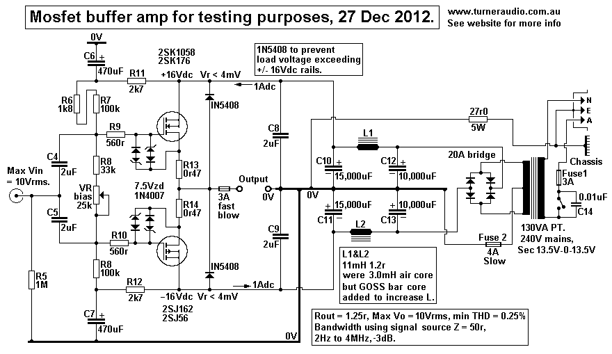
Fig 6. Mosfet buffer amp.
schem-12W-mfet-buffer-classA-AB-27dec12.gif
Fig 6 buffer stage allows adequate testing of any audio transformer at F above core saturation, say 2Hz to over
4MHz where load is above say 4r0 where class A action occurs up to 5.6Vrms output. I have a 3A fuse to
prevent excessive output Iac and 1N5408 to limit back emf > 16Vpk from any load connected.
Testing L load down to VLF is possible with care, and C load up to HF.
For a 100W into SMT primary for 16r0, there is 40Vac needed. The F response with sec load can be done
with 4Vrms.

But Fsat can be found using a variable 50Hz Vac from mains and if the SMT has Fsat = 14Hz at 40Vac input,
then at 50Hz there will be Fsat = 142Vac.
To view the onset of core saturation, a series current sensing 1r0 is connected between earthy end of SMT
and 0V buffer terminal. A CRO monitors the Iac in 1r0, and at Fsat the distortion rapidly increases when Vac
frequency is lowered just below Fsat.
The SMT tested should have XL = primary RL at 14Hz or less, so for 16r0, L minimum 0.18H. At 3Hz, XL
= 3r4 so Iac = 1Arms with 3.4Vrms input, and nothing cooks, and no fuse blows.

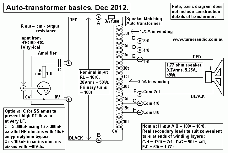
Fig 7. Auto-transformer basics.
auto-transformer-basics.gif
Fig 7 shows a very basic set up of amplifier powering a speaker with an SMT connected. The advantages of
auto-transformer are that winding resistance losses are lower than isolation transformers for where the secondary
load is not less than 1/2 the primary load. In above auto transformer, the non-shared portion of winding A to E
and F to B has input current = 1.75A for the 120t, and if the Rw = 0r5, the power lost = 1.53W.
Iac in the remaining E to F shared "secondary" winding will be found = speaker load current 5.25A - 1.75A input
= 3.5A. The turns for E-F = 60t, and if the same dia wire exists for all windings, Rw = 0.25 ohms and losses
= 3.06W. Therefore total P+S losses = 4.6W, ie 9.2% of 50W applied to input. The above diagram shows Po
at sec = 49W which is extremely optimistic and in fact one would get Po = 45.4W approx.

If an isolation transformer were to have a primary winding of 180t using the same wire wire size then more bobbin
window area must be found for the 60t for isolated secondary, so the window size must be larger. This involves a
larger core size, but with lower stack height to keep Afe the same. But weight has increased. And turn length may
increase. The 180t for primary carries 1.75A and Rw may become 0r9 so losses = 2.75W. With 60t for secondary
using same wire size, Rw = 0r3 and current is the same as for speaker at 5.25A so sec winding loss = 8.27W,
so total P+S losses = 11.0W. Total losses are about 18%. Po at sec = 39W approx.

To reduce losses for BOTH types of transformers requires slightly different methods. For the auto transformer,
the winding E to F would in fact comprise two paralleled windings each 60t. This would halve sec losses to 1.53W,
and total P+S loss = 3.06W, or 5.7% of 50W of input power. This means that there would be 8 layers of wire
with two of them paralleled with another two for between E and F and these 4 windings would then be spread out
among the remaining 4 to minimize leakage inductance to get best bandwidth.

The isolation transformer would need to have a much bigger window, AND to get lower resistance losses the wire
size must also be increased AND to reduce the number of turns for same Fsat the stack height must increase.
The secondary would need to have paralleled windings and/orlarger wire size than the primary. I cannot give all
details but you will find the conventional isolation transformer will need to be twice the weight of the auto
transformer to achieve the same power handling, Fsat, and winding losses, and an example of isolation
transformer is below......
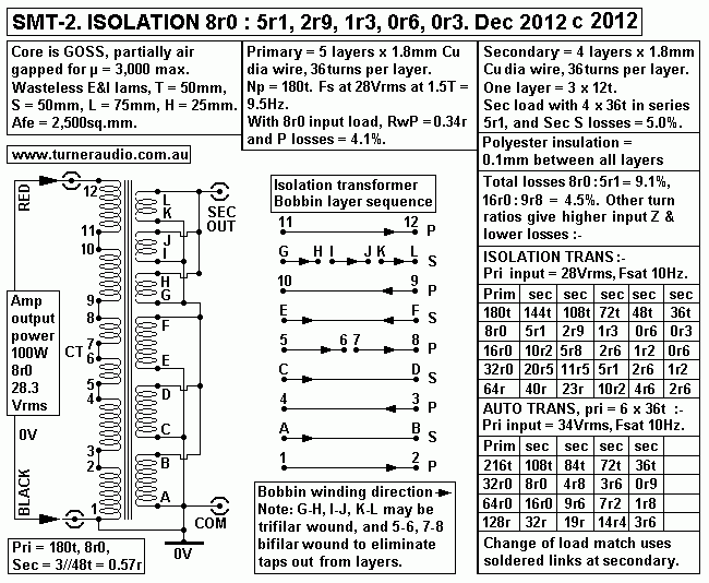
Fig 8. SMT-2. Isolation transformer.
SMT-2-100W-isolation-trans-2012.gif
In order to get reasonably low winding losses with the isolation SMT, the core size must have a larger window
size to accommodate larger winding wire. Should anyone wish to have the primary used with a Vdc potential of
say up to 100Vdc, they can do so safely without worrying about the secondary and speaker also being at a
Vdc potential. But I draw the above with both P and S windings taken to 0V at one end. The sec windings are
in a wasteless pattern so sec load matches are changed with soldered wire links on a terminal board on one side
of SMT. Some audiophiles understand my reasons, but many do not, and find altering sec links to be a Royal
Pain in The Arse.
There are 12 pri connections numbered 1 to 12 in winding order and all connected in series. There are 12 sec
connections, A to L. I have not included details of how you would arrange a circuit board allow an easy change
of P to S turn ratios, but one method has 2 recessed 4mm banana sockets for primary input and another 2 for
secondary output, and an octal socket for use with differently linked octal plugs to alter how sec windings are
linked.

This works just fine if the system owner wants 16r0 load for whatever amp he has, and has 3 octal plugs each
clearly labelled for 2r0, 4r0, 8r0, so he must try not to lose the 4 plugs he is not using, and over say 5 years
I would think nearly all owners would lose their plugs.
The autoT above allows 28.3Vrms input to 8r0 for 100W with 9.1% winding losses and Fsat 9.5Hz.
If the input load = 16r0, you could have 56Vac input for 200W, and Fsat = 20Hz, and Rw loss 4.5%.
If the input load = 32r0, you could have 56Vac input for 100W, and Fsat = 20Hz, and Rw loss 2.2%.

One might be tempted to make the SMT secondary in the form of say 4 parallel windings each with taps and
just like a tapped secondary on a tube amp OPT. But this means the core window must be even bigger to
accommodate more turns, and by then the use of a plain old auto SMT with no isolation between P and S
begins to make a whole lot more sense. So I have not given any more details, and I leave that to others.

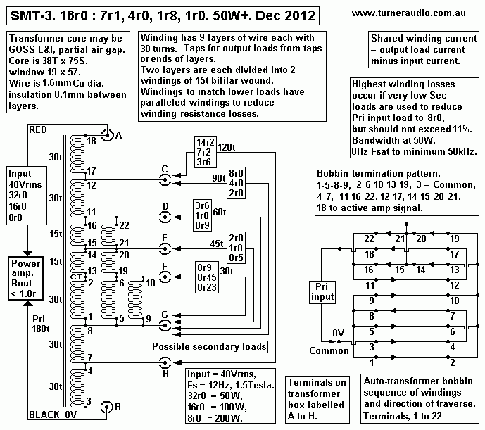
Fig 9. SMT-3. A fairly simple auto-transformer for 50W. :-
SMT-3-50W-auto-trans-2012.gif
Fig 9 shows the schematic for SMT-3 to make a range of speaker loads "look just like" a higher Z speaker from
the amplifier's view point. There are 5 sets of load matches shown for each of 3 nominal values of SMT-3 input load.
Suppose the wanted amp load = 32r0. Plug cables from amp to A and B on SMT-3 input.
Plug cables from speaker to the terminals shown :-
C to H = 14r2, C to G = 8r0, D to G = 3r6, E to G = 2r0, F to G = 0r9.
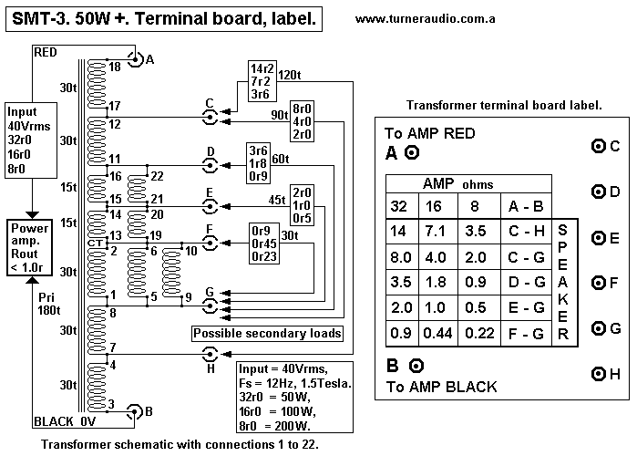
Because there are 5 possible load ratios it would be very easy for someone to use the wrong terminals. They may
use different terminals for each channel, and I suggest everyone should triple check every thing they do.

However, as long as amp cables go to A and B, then connection of any speaker to between any of the terminals C to H
will always give a higher load ohm value between A and B. If anyone remains confused, I suggest they consult a more
logical friend.

With input = 40Vrms the Fsat = 12Hz where Bac = 1.5Tesla. It means that the SMT could cope with 200W of input
to 8r0 looking into the SMT-3 A and B input. 
Winding losses are highest when input load is lowest, say 8r0 between terminals A and B, and where output load
is lowest, 0r22 between E and G. See Table 4 below Fig 10.

Confused by so many connections ? here is a board layout and label :-
Fig 10. SMT-3 terminal board.
SMT-3-50W-terminal-board.gif

Table 4. SMT-3 Input to Output loads, total winding loss %.
Terminals A-B
Primary 180t
C-H
120t.  
C-H
Rw
loss %
C-G
90t
C-G
Rw
loss %
D-G
60t
D-G
Rw
loss %
E-G
45t
E-G
Rw
loss %
F-G
30t
F -G
Rw
loss %
32r0 50W 14r2
0.6%
8r0
1.2%
3r6
1.7% 2r0 2.3% 0r9 2.8%
16r0 100W
7r2
1.3%
4r0
2.3%
1r8
3.4%
1r0
4.5% 0r45 5.5%
8r0 200W
3r6
2.5%
2r0
4.6%
0r9
6.8%
0r5
9.0%
0r23 11%
S : P Load Ratio
x 2.22 

x 4.0

x 9.0

x 16.0

x 36.0


Most uses will not have a speaker Z lower than 2r0 and total winding loss wil not exceed 5%.
-----------------------------------------------------------------------------------------------------

Only a few people get very nervous about connection of a speaker load with resistance < 16r0 across the
output terminals of any amp such as OTL with tubes, or bjts or mosfets, all without an outpur transformer.
Most ppl remain entirely unaware of any danger to the amp especially if it is a solid state amp. SS amps have
become much more reliable than they were in 1965 when nearly all SS amps had a 2,200uF capacitor between
solid state circuitry and the speaker load.
After about 1980, nearly all SS amps were DC coupled with their highest open loop voltage gain > 20,000 and
0.0Hz. The GNFB network kept Vdc at SS device output at very close to 0Vdc, and with or without any load
connected. bor The GNFB network of 300W class AB amp can be seen at Fig 1 at
solidstate amps 1 mosfets.

The low winding resistance of the primary of any SMT is much lower than the winding resistance of a speaker coil.
Tube amps with normal OPT isolation transformers cannot transform Vdc or Idc, so tube amps can only overheat
a voice coil with excessive Iac, which seldom occurs.
But an SS amp or tubed OTL with direct connection to speaker with voice coil Rw > 16r can be subject to problem
of excessive idle Idc in devices or unbalanced Idc in PP devices. If theVdc offset at output was +0.5Vdc without any
load, the NFB may try to maintain the +0.5Vdc with all loads, and if speaker voice coil Rw = 5r0, there is 100mA
flow in voice coil. This is not enough to cause audible HD or IMD at low levels, but with SMT the Rw of a primary
could be 0.4r0, and there will be 1.25Adc flow in SMT where Vo = +0.5Vdc, and Idc flow in 2 series devices will
be grossly unbalanced.

Post 1980 direct coupled SS amps do not need any pot for adjustment of Vdc offset; the GNFB ensures Vo terminal
at devices is extremely close to 0V no matter what R+C+L load is used.
But many other SS amps and tubed OTL amps needed to have a pot to set Vdc offset to 0V before connection of
any load.

Where a pair of Series PP triodes has rails of +/- 150Vdc, the output Vo is usually from cathode of upper triode to
anode of lower triode which are joined at Vo. Direct coupling and a GNFB network to keep Vo at 0Vdc has never
been used
and would be far too complex to justify trying to do it. Therefore many OTL schematics with Series PP show a pot
to adjust the Vdc grid bias of output triodes get Vo to 0Vdc. The adjustment drifts with time, so with directly coupled
speaker voice coil or SMT, Idc flow from amp to load can become significant to upset the balance of idle Idc in the
two output triodes.
If both output triodes are biased for 25% of rated Pda, they become prone to overheating if there is a +/- Idc flow
from Vo to 0V.
One triode may have too much Idc and overheat while other triode has too little Idc and runs cool. This may cause the
amp to perform as a badly designed single ended amp for the first few watts, and THD+IMD will be much too high.
To avoid such problems with tubed OTL or some SS amps, a DC blocking cap can be soldered inside the amp
between amp output terminals and output from devices.

The Sugden A1 amp with two series N type power bjts has +47Vdc rail only, and Vo from upper emitter and lower
collector is at +23Vdc. There is no need for +/- rails and a 10,000 uF electro cap used has 63Vdc rating. The same
1969 circuit was still being used in A1 in 2012 when I had to massively modify one that had caused its owner no end
of troubles. When I emailed Sugden, I got told "We have always done it that way and we are not changing, and we
have sold more amps than you have...etc". OK, some designs will never change, but I had to deal with audiophiles
who were much disapointed by the Sugden A1.

But Sugden's use of 10,000uF output C is a very valid circuit method, and Idc flow from Vo to 0V via low voice coil
Rw or an SMT winding is entirely avoided. The highest Vdc possible across the C = 47Vdc if one or both bjts fail.

But where 2 triodes or two mosfets or bjts work from +/- Vdc rails and have their Vo point near 0Vdc, the Vdc
across an electrolytic C is too low for correct polarization, and one way to get enough Vdc is to use 2 x 10,000uF
el-caps rated for 63V each and in series with their + terminals to ampVo and load, and both - terminals connected to
10k R taken to -35Vdc. This biases both 10kuF to have 35Vdc. But if Vo at amp ever swings to +/- 150Vdc, caps
will be wrongly biased and the MUST be an active protection circuit to turn off the amp if device Vo point ever goes
to more than +10Vdc or -10Vdc for longer than 4 seconds.
With 2 x 10,000 uF in series, the total C = 5,000uF, and if speaker = 4r0, the LF pole is at 8.0Hz which is OK.
The amp NFB MUST be from Vo point of device circuit, so that the 5,000uF is a passive element. See the wes
catalog pages at https://www.wes.com.au/mediapub/ebook/wescat2017np/#1400
The largest bipolar el-cap is 470uF rated for 100V.
-----------------------------------------------------------------------------------------------------------------
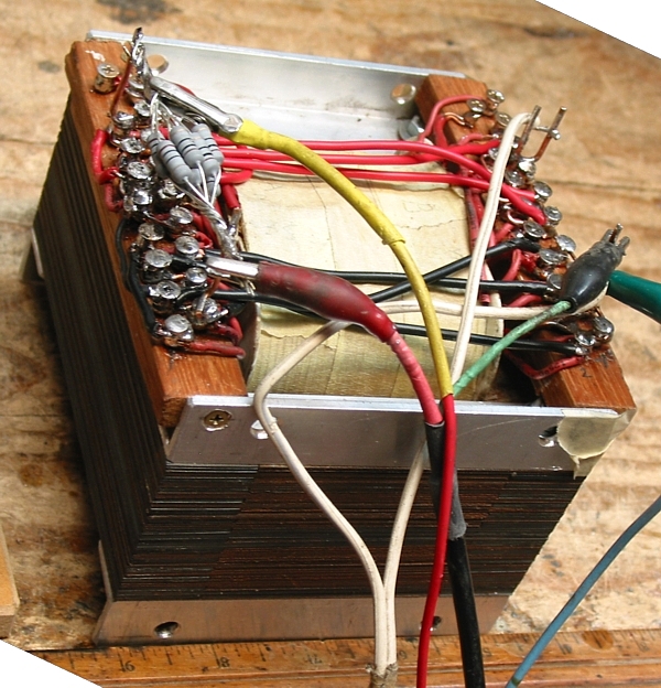
Fig 11. SMT-4 Prototype 100W on bench under test.
SMT-4-picture-1.jpg
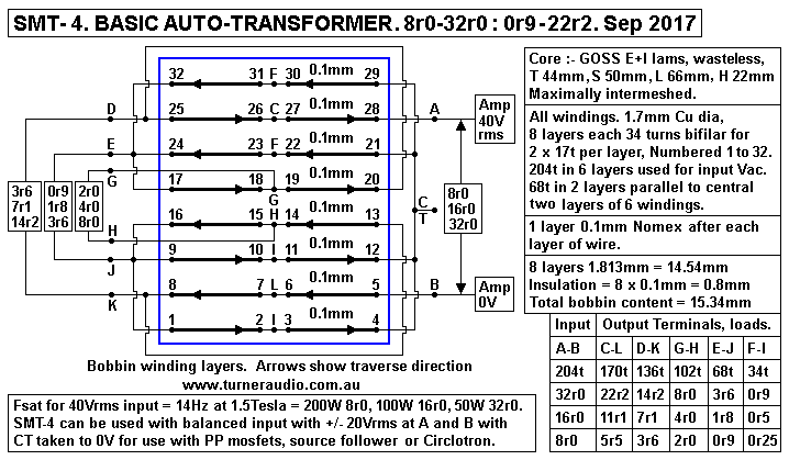
Excuse the somewhat messy appearance of SMT-4 prototype. There are 8 layers of 1.7mm Cu dia wire,
with 34 turns of wire per layer, and each layer is bifilar wound so there are 16 windings, and are terminated
at 16 terminals on each side of bobbin.
The bifilar windings allowed a large number of possible impedance matches and allowed experimentation
with interleaving patterns for highest HF with R loads and lowest winding losses.
It is extremely easy to become completely completely confused by any transformer with 16 windings and 32
connections.

Fig 12. Basic information for SMT-4 pictured in Fig 11.
SMT-4-100W-auto-trans-basic-16rPri-many-loads-Sep-2017.GIF
Fig 12 shows all details of SMT-4 about as simply as possible. The bifilar wound layers allows for a CT to each
layer without having two wires from 1/2 way across the bobbin to got outside the bobbin cheeks and cross over
other turns at 90 degrees. Both 17t windings of each bifilar layer traverse the full bobbin width. It was easy to wind
17t across bobbin and leave a gap between all turns. A second 17t is wound on between the turns of first 17t and
to get wire to all lay well, a plastic paddle is used to sway turns togehther or apart to end up with a nice flat layer
with 34t.

Some possible additional load matches and links are not shown. Where I show F + F and I + I they may be linked
to get the 34t for F-I. I also show C and L in middle of windings for 170t which transforms speaker 5r5 to amp load
of 8r0 which is not hugely useful as the ratio for 136t where you get 3r6 transformed to 8r0, which allows many ppl
to happily use their 4r0m speakers at amp output meant for 8r0, or perhaps use the amp output labeled 4r0, which
would make most power pure class A with better sonic results

It is also possible to connect a speaker to D-L

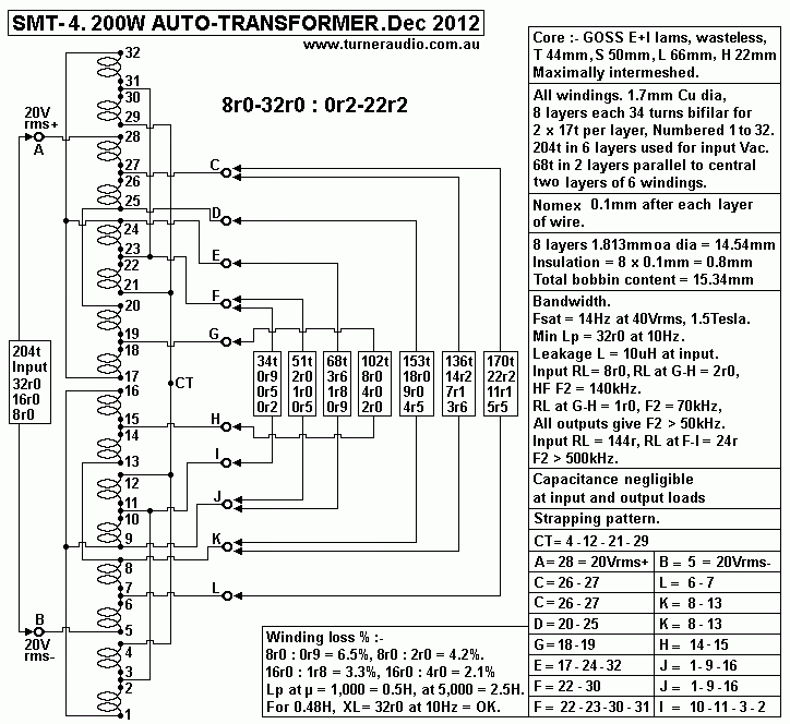
Fig 13. SMT-4, more details for auto-transformer.
SMT-4-200W-autotrans-8r-32r-to-0r2-22r-2012.gif
Fig 13 includes more details for SMT-4, but is more confusing, even though there are only 8 layers of 34t
each, 1.7mm Cu dia wire.

Although it is not obvious in the above schematic of the transformer, the outermost layers 1-2-3-4 and 29-30-31-32
are in parallel with layers 9-10-11-12 and 21-22-23-24. The positions if these 4 layers are symmetically placed
between the remaining input layers in series 5-6-7-8 plus 13-14-15-16, and 17-18-19-20 plus 25-26-27-28.
The interleaving at I show it gave HF extension to at least 50kHz for the highest ZR ratio with 8r0 input : 0r2,
with all more commonly used ratios of say 8r0 : 2r0 giving 140kHz. This means the maximum effective number of
turns between A and B = 6 x 34t = 204t. Total turns = 8 x 34t = 272t.

The paralleled windings have more copper section area to suit low loads for least winding losses.
The transformer may be used with a normal single ended amp output with an active Vo terminal and  a 0V terminal.
I show balanced input, but the operation is the same for SE.

SMT-4 could be used in a PP amp where only N type mosfets are used in source follower mode to drive each end 
of the SMT-4 with the CT taken to 0V, and balanced Idc flow will be in each symmetrical 1/2 of the winding.
If there are 8 mosfets biased for class A, and each is biased for idle Pdd = 16W, we could expect 7W class A with
56W total class A Po. If the Vs-s across winding = 28.3Vrms, then SMT4 input load = 14r3. Each mosfet will
have Vd-s = 14.2Vrms, and make 7W so its RLs = 28r8. Iac = 0.49Arms, so idle Id = 0.7Adc, and Ed = 23Vdc.
If Ed = 33Vdc and Id = 0.5Adc, there is substantial class A Po plus high much higher class AB. The mosfets will
sound a lot better than a large number of power hungry triodes in an OTL arrangement.

The SMT-4 thus can be used as an Out Put Auto-transformer which I can call an OPAT, a name not given
by anyone else to this transformer application.

The simplest use of above SMT-4 is where A and B are connected to Com and 8r0 terminals for many PP tube
power amps which have been badly designed to make absolute maximum Po when 8r0 is connected which forces
the tubes to spend most of their life working in their most non linear region to generate a small amount of class A
and a high amount of class AB which may never be used by the owner. Amp designers are told to make their amps
produce huge Po which is more likely to be sold to customers who are entirely ignorant about anything technical.
16r0 would be a better load for the Com-8r0 terminals, and use of SMT-4 allows 9r0, 7r1, 4r0, 1r8 speakers to
be used which gives 16r0 input load.

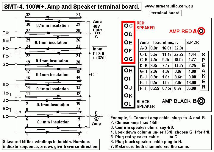
Fig 14. SMT-4. Speaker terminal board.
SMT-4-100W-amp+spkr-terminals2-2012.gif
Fig 14 shows the wire link connections made on the 32 terminals mounted on the transformer with 16 on each
side. Also shown are the wire links to the underside of 4mm banana sockets A and B for amp and C to L
sockets for 4mm speaker cable banana plugs. The banana sockets should be mounted on a vertical board fixed
to transformer case so all terminals may be easily seen when standing behind the equipment stack.

The SMT-4 should be enclosed in a plywood box using 17mm marine ply, and well screwed and glued with one
aluminium vertical side panel drilled for recessed 4mm banana plugs for A to L with red or black plastic color. 
The table for load ohms and other labels should be made up to be well glued to Aluminium plate and varnished.

A sheet steel box could also be made with one removable side and with 12mm clearance between box to core
or windings. This should be filled with dry sand before plate with wiring is screwed on to prevent box sides
vibrating. The steel box offers good magnetic shielding, but SMT should be placed well away from other gear
on the equipment stand, or just behind the speakers on the floor.  

SMT-4 Test Results. I tested the above transformer using the mosfet buffer and 3Vrms sine wave signal source
from 2 generators giving 2Hz to 4MHz bandwidth, with Rout of buffer = 1r3. With no load of any kind connected,
bandwidth for between G and H was dead flat from well below 10Hz to 1MHz, with a +1dB peak at 900kHz.
There was a peak of +3dB at 2MHz and then output declined at more than 12dB/octave with other peaks and
nulls of lessening levels. Use of a 465kHz square wave showed some slight ringing frequencies between 4MHz and
10MHz.

There were no problem resonances below 1MHz. Pure C load of 2uF produced no large amount of ringing, and
was better than many other audio transformers.

F2 -3dB points at HF with pure R loads at G-H were 4r0 = 240kHz, 2r0 = 140kHz, 1r0 = 70kHz.
For other loadings with higher input resistance the HF F2 was slightly higher. Leakage L at primary < 10uH.
Shunt Capacitance = negligible. 

With Np = 204 turns for the SMT, Afe = 44mm x 50mm, µ max = 8,000, and ML = 245mm, and at high signal
levels at 50Hz, max Lp = 4.0Henry. Lp is far larger than it needs to be but at very low Vac levels of less than
0.5Vrms at input for much normal listening the minimum iron µ may be as low as 1,000 which gives Lp = 0.5H.
This is OK because Lp has XL = 32r at 10Hz, so the amp load becomes 22r at 10Hz which causes no problems.

SMT-4 is capable of much more power than most tube amp produce. One may like to think it possible to use
SMT-4 for a 30W SE amp with Idc 3.2A with a well gapped core. 4 x N type mosfets in class A could be used
in source follower mode with SMT between sources and 0V. But with total Rw = 0.345r, Vdc across winding
= 1.1Vdc, and connection of any speaker will cause Idc flow in speaker so speaker must be coupled to SMT
with 10,000uF which is an added problem to be avoided. I suggest trying to use SMT-4 for SE use is not
worth trying to achieve and PP operation is much better.

With no unbalanced Idc present, the core saturation behaviour determines quantities of iron and turns, not Lp.
My GOSS core with maximum intermeshing of lams has µ = 17,000. But I divided E+I lams into sub-stacks of
7E and 7I in which 7E face one direction. Each sub-stack was assembled into bobbin hole in alternating directions
which reduced µ max to 9,000, and if the core had sub-stacks of say 15E and 15I, perhaps µ max would be
between 3,000 and 5,000, thus further reducing risk of saturation with stray LF signals below 10Hz with high
amplitude. Most audio recordings do not contain such stray LF waves. And amplifiers should be made to have
very little gain below 5Hz, so that intermittent connection of preamps or phono amps does not cause any devices
to fuse with large LF currents.

Are there any questions?
-------------------------------------------------------------------------------------------------------------

Definitions of terms used here :-
R is resistance in ohms, and R = V / I where V is voltage in volts applied across R, and I is amps of current
flowing through R as a result of applied V.

RL is Resistance Load, which is the resistance of a wire or manufactured resistor used in a circuit where active
devices such as vacuum tubes or solid state cause a change of current to to liberate power.

RLdc = load between a DC supply rail and a tube anode or cathode to change current.

RLa = load for ac power produced at an anode.

RLa-a = load for two push-pull anodes of two tubes supplying opposite phased voltages to each end of RLa-a.

P is the symbol of power as heat measured in watts calculated P = V x I, or V squared / R or I squared / R.

Po = power output.

Pin = power input.

L = inductance in Henrys, millihenrys, mH, or millionths of a Henry, uH.

Lp = primary inductance of a primary winding.

Lsec = secondary winding inductance.

LL = leakage inductance between two windings.

C = capacitance in Farads, F, millionths of Farads, uF, or billionths of Farads, nF,
or 1,000 billionths of a Farad, a pico Farad, pF.

X is Reactance in ohms for either L or C. The ohm value is only valid for only one sine wave frequency.
Reactance value of C = XC, and of L = XL.

XC = 1,000,000 / ( 2 x pye x Frequency in Hertz x C in uF ) = 159,000 / ( F x CuF ) r, ohms.

Hertz = frequency measured in cycles per second, Hz, or kilocycles per second, kHz, or millions
of cycles per second, MHz.

XL = 2 x pye x F in Hertz x L in Henry = 6.28 x F x L r, ohms. pye = 22 / 7 = 3.1428

Ra = dynamic anode resistance in ohms, r.

µ = amplification factor of a vacuum tube. µ = gm x Ra, where gm = transconductance Amps / Volt, Ra in r

gm = device transconductance in A / V or mA / V.

µ = also means iron core permeability, a number that varies with F and applied Vac so context of µ must be
remembered.

Z = impedance, nominated in ohms, and for any combination of R, L or C connected together and such parts of
circuits with R plus L and / or C are called networks. The impedance of any network measured between any two
points is dependent on frequency of the sine wave voltage applied from one point to another. The calculation of
impedance between two points connected to more than one R and L and C can be almost impossible to work out,
and is best calculated using software and PC, although simple R+C and L+R networks can be easily calculated.
But without computing, an approximate estimation of Z may be made and values trimmed by measurement until
wanted F response and Z is obtained. The following formulas don't include frequency F. But ohm values of XC or
XL do include frequency.
I make no apologies for saying you have to consider many things if you are to make accurate calculations about
L+C+R networks, and you must be careful when measuring them. Its no use chucking a tantrum when I expect
you to understand details and to calculate and consider things that are not simple !!!!!.

For example, For R+C in parallel, Z (R // C) of network = 1 / square root of ( 1 / R squared + 1 / XC squared ),
Z in ohms r, R in ohms r, C in Farads.

For R+C in series, Z ( R+C) = square root of ( XC squared + R squared ) in ohms where R is ohms, r,
C in Farads and XC in ohms, r.

Similarly, for R + L in parallel, Z ( R // L) = 1 / square root of ( 1 / R squared + 1 / XL squared ) ohms, r.
For R+L in series, Z ( R+L ) = square root of ( R squared + XL squared ).

Eg, XC for 2uF is 79.5 ohms at 1kHz. Impedance of say R = 79.5r plus 2uF in parallel is 56.2 ohms.
Where XC = R then XR // C = 0.707 x R.
In series, 79.5r plus 2uF has Z = 112.4r. Notice the X ( C+R ) = R x 1.414.
You will have to study many more examples plus a mountain of theory and equations for which I don't have time
or space to include here. Many keen audiophiles are utterly dumb and unable to consider the world in terms of
applied mathematics, and its why their own attempts and designing gear are so ineptly incompetent and bad
sounding, and likely to generate smoke.

Back to
Index Page
Educational and DIY directory