SE32
with 13E1, CFB, 2012 version.
Schematic 1, SE32, April 2012 version......
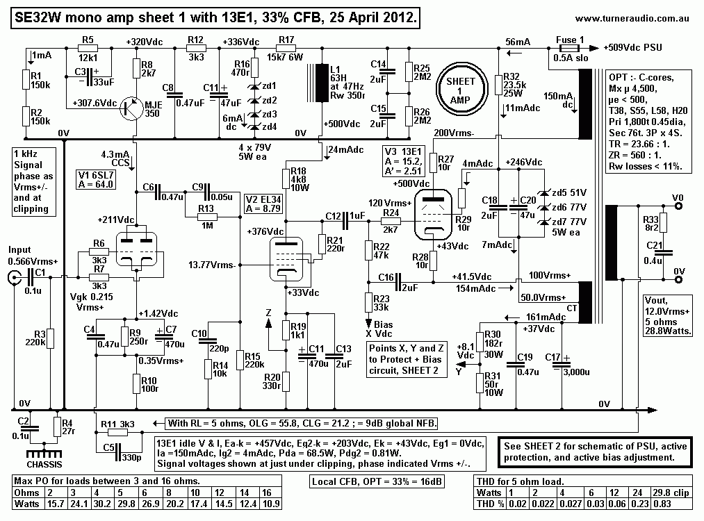
The above Sheet 1 Mono Amp has similar operation to earlier SE32 from 2008.
The differences are :-
1. +750Vdc rail and 25k RLa for dc to EL34 is replaced with 60H
Choke + 5k resistance
from B+ rail = +509V. EL34 Iadc increased from 16mA to 24mA.
2. EL34 THD reduced due to high RLa ohms and to more linear
working point.
3. EL34 Rk has been fully bypassed, to lower the effective Rout of
the stage, thus improving
micro-dynamics at higher F. Gain is slightly increased.
4. The 68k RLa for dc to 6SL7 is replaced with CCS using 1 x
MJE350, thus much increasing
the Ia and anode load ohms to increase gain from 48 to 64, while
much reducing THD.
5. 13E1 cathode R&C bypass network and CFB OPT winding is
changed.
6. Eg2 increased from 170Vdc to 200Vdc. Active automatic bias
voltage adjustment is applied to
13E1 grid to allow for variation in samples of tubes selected for
use and for tube aging and variations
in static grid current causing grid bias change and elevated Ia.
7. Many other minor changes and tidying up of circuitry.
8. The open loop voltage gain of the whole amp is increased by a
total of about +4.5dB.
The amount of global NFB has been kept the same at about 9dB by
means of changing the GNFB
resistance divider to reduce ß, ie, the fraction of output fed
back to V1 cathode.
The 2008 amp needed 0.88Vrms input for clipping with 5 ohm load,
but now only 0.57Vrms input is
needed so that preamps are not needed and signals from a CD source
may fed directly to the amp via
a 20k log pot mounted in a metal box with source selector switch,
in what is also known as a "passive
preamp", ( which is misleading, because nothing is amplified or
passed through any active device within
such a box. )
9. A fraction of the EL34 cathode bias voltage Ek at point Z is
taken to the protection circuit in case of
an EL34 having bias failure.
10. The 13E1 cathode biasing RC network has been arranged so
R&C network is grounded with
local CFB winding on OPT now between cathode and R&C network.
11. A fraction of the Ek is taken from Point Y to the active auto
biasing and protection circuit input
points shown on SHEET 2 PSU. The variable bias voltage for 13E1
grid from BC327 on SHEET 2
is applied at point X.
12. C16 is added to bootstrap the bias Rg R22, 47k. This
resistance then effectively becomes a much
higher value of ohms at signal F of 280k, so its loading effect on
EL34 becomes negligible.
This reduced the 2H of EL34 enough to give a welcome reduction of
overall 2H at high speaker load
values where 2H of the EL34 adds to the 2H of the 13E1, so that 2H
cancelling does not occur.
The effect on 2H of bootstrapping or not bootstrapping R22 was
measured. The bootstrapping
gave better overall results than not bootstrapping so it has been
retained. The increase in screen
supply voltage gave slightly less THD with low value loads, but
the Rk at 13E1 needed to be
increased from 185r to 232r to get a slightly higher Ek so that
the centre value grid biasing voltage
remains at 0V with Ia at 150mAdc. There is a slight reduction in
maximum PO but the 13E1 should last
longer and be less likely to overheat. Using a CCS with a
transistor to replace R30,R31 Rk was
considered but thought to be unnecessary over-engineering.
Schematic 2, SE32 PSU, April 2012 version......
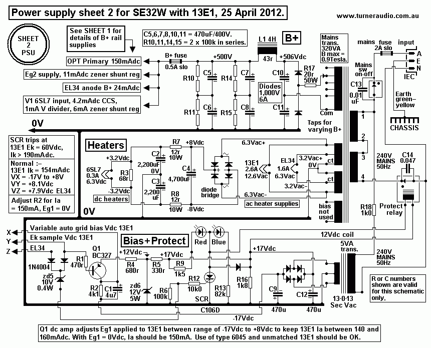
The above Fig 4 PSU sheet 2 schematic needs little explanation for
the basic rail voltages supplied by
the main large power transformer.
There is a second small auxiliary 5VA power trans shown which
powers the Bias+Protect schematic.
There are two inputs to the circuit from resistance dividers in
the cathode R&C biasing networks of
EL34 and 13E1. The active protection is based on using a faction
of Ek of EL34 or 13E1 to turn on a
sensitive gate SCR, C106D, if too much Idc flows between cathodes
and 0V. The large mains transformer
has its mains primary winding switched open with a relay operated
by the SCR. The "on" blue LED goes
out and red "fault" LED turns on. Owners can try to reset the amp
by just turning off, waiting 2 seconds,
then turning back on.
But if an underlying problem remains present, the amp will just
turn off again.
Over many years I have discovered how much damage has been stopped
in many amps where tubes
have failed or shorted speaker leads or faulty speakers have been
used.
The new addition in this bias+protect schematic is the use of Q1,
a pnp BC327 transistor which
constantly controls the Idc in 13E1 in addition to the R&C
cathode biasing network.
The Y input from 13E1 R&C bypass network is taken from join
between R30 & R31 on amp sheet 1
and applied to a base of Q1, BC327, through a base current
limiting R of 470 ohms.
This voltage normally about +8.2Vdc. The BC327 emitter has 680
ohms to a fixed +12Vdc.
The BC327 collector has 4k1 taken to a -17Vdc supply rail.
The bias current for the BC327 is 5mAdc.
The 13E1 grid bias voltage is derived from the collector voltage
of Q1, and sent out via path X to a
33k then to bias resistance of 47k The Q1 collector load R1, 4k1
is bypassed with C1 4u7, thus the
33k and 4u7 form a filter preventing high level audio signals at
13E1 cathode appearing at Q1 collector.
There is about 0.022Vac ripple voltage at -17Vdc rail and at Q1
collector, and this is prevented from
appearing at the 13E1 grid because join of 33k and 47k is bypassed
with the 2uF bootstrapping C16 on
sheet 1.
In effect, the whole arrangement shown prevents unwanted signal
flows in 2 directions. The gain of Q1
is highest at very low F, and only about 5.5. If the Idc flow from
13E1 increases say 10mA, then Vdc
at point Y will rise by +0.5Vdc. This will appear at Q1 base and
be amplified x 5.5 to cause a correction
voltage of -2.75Vdc to be applied from point X to the grid. If the
tube transconductance = 20mA/V
then the reduction of tube current would be -55mAdc. In fact, the
Q1 acts to regulate the Ek Vdc appearing
at 13E1 cathode, and thus keep Ek more constant than if a much
larger value of Rk was used, or if a an
active cathode current sink were used.
For example, I tried a couple of CV6045 of unknown brand and with
the ordinary cathode R&C network
used for the 13E1 made by ITT. The Ia went up to 180mA, and Pda
went to 83W, which is TOO MUCH.
With the active Q1 bias regulator, Ia remained less than 160mA,
with a few -Vdc applied to grid, and Ek
remained close to where it should be.
In other words, the Q1 circuit acts to provide DC feedback. The
time constants chosen for R and C parts
ensure the bias trimming circuit is not unstable at some low F
which can so easily be a very real problem
if the time constants are ill-chosen, or the the gain of the
transistor is too high to try to get absolutely perfect
bias control.
The arrangement for 13E1 cathode biasing and screen supply has all
the current supplied to the screen and
through the shunt regulating zener diodes. So if any variations to
Ig2 occur, then Ek will not change as a result.
It the screen was ever to short circuit to cathode, or more
likely, the bypass caps between screens and
cathode short circuit, then maximum current through screen supply
resistance R32, 23k5, sheet 1,
is 21mA, only 10mA more than normal. The tube would not work if
screen supply voltage reduces to the
same as Ek at cathode.
Without the active grid biasing adjustment, the bias current of
13E1 is completely dependent on the R&C
biasing network. This R&C bias network does not have a very
high amount of resistance, so some help to
avoid problems with biasing from one lone easy-to-get transistor
is very welcome, and in fact, forgivable,
because try hard as you wish, but its presence is utterly
inaudible, while helping the music to be better
sounding, just for you. The other feature of my new biasing
circuit has the biasing R&C network subject
to all the screen current plus the current through the zener diode
shunt regulators. At idle, about 12mA
flows from B+ to screen and zener diodes.
During normal operation, the total of 12mA does not vary even if
screen current input were to vary
between a normal 4mAdc at idle to 12mA at high levels. The shunt
regulators tend to keep Ek more
constant than if they were not used, or if zener diode current was
not included in in the flow through
the R&C biasing network as shown for the 2008 schematic.
The other source of class A tube amp bias problems can be due to
mains voltage variations.
Triode and UL amps are most prone to enduring higher than wanted
Ia with abnormally high mains Vac.
If an amp has been designed badly with mains primary meant for
only 110Vac to suit USA and 220Vac
for everywhere else, then just 2 x 110Vac windings can be in
series or parallel to suit the national Vac.
But here in Oz, I have often measured 255Vrms and when used with
an amp with 220V transformer,
the heater voltages rise from the correct 6.3Vac to 7.3Vac, and
Vdc can rise from the intended +400Vdc
to +463Vdc, and if the Idc flow was a normal 70mA in an output
tube with a well regulated bias voltage
supply, then Ia might rise from 70mA to 85mA, and tube Pda rise
from 28W to 39W, and this can place
tubes very close to their Pda limit. With many hi-end and low-end
brand-name amps I have seen tubes
fail due to overheating when the amps are used here.
Therefore, it is WRONG to regulate grid bias voltage supplies
because if the mains voltage is too high,
then you want the bias to increase with mains voltage increase and
this tends to compensate the effect of
having a high mains voltage.
Alternatively, if the mains voltage is lower than normal, the grid
bias voltage may be less to allow more
Ia to flow. In my schematic above, the +/- 17Vdc rails are not
regulated, and if the mains voltage is high
then -17Vdc rail becomes more negative, and tends to reduce
excessive Ia. At dc operation, the Ra of
the 13E1 tube is very high, perhaps 10,000 ohms because the screen
is shunt regulated and kept at a
constant voltage above the cathode voltage. With 13E1 used in
triode or UL, Ra is less than 1,000r,
and a rise of 50Vdc in Ia would cause a rise in Ia of maybe 50mA
which could make Pda very excessive.
With my active biasing adjustment, and with shunt regulated Eg2,
there will be few problems with any
variations in mains voltages.
The 2 amps in which this bias scheme has now been employed were
brought to me a couple of months
ago for a service, the first since 2008. I advised my client that
more could be done to improve
performance, so the 2012 schematics were evolved.
The amps had been used very often, and the owner sometimes had
them running for days on end.
A colleague told me the rated tube life for 13E1 is around 2,500
hours. The first pair of 13E1 had lasted
from 1997 to about 2005, and this last pair from 2005 to now, and
from what I know, the hours of use
have much exceeded 2,500. All 4 tubes used since 1997 were ITT
brand. In the two last tubes, the
operation of both were flawless and without reverse grid current
or fading emission and both were able to
give a full 31W+ of power, and bias remained stable.
However, the gettering in one tube shows considerable browning and
aging, while in the other the
gettering has almost all become transparent but muddy brown, so
both these tubes will be replaced with
NOS with nice clean bright silver gettering. The result of all the
alterations should raise the sound quality
to be equal or superior to my SE35 amps with a quad of EL34 output
tubes.
Gettering wear indicates tube condition....
Image 2, May 2012.
Looks unused-----------------------------Looks a bit
worn--------------------------Looks worn out
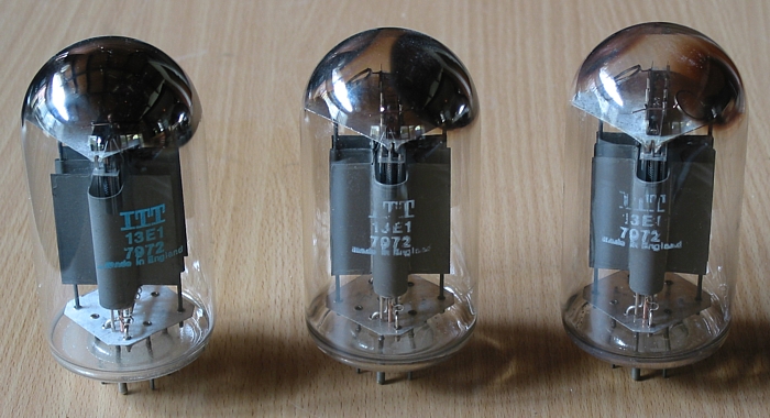
On the left side of the picture, there is a NOS 13E1, never been
used.
The two other tubes were installed in around 2006, and they show
classic signs of gettering change
from the clean bright silvering on unused NOS tube.
The metallic content of the worn tube gettering has partially
combined with gas entering the tube through
join between base pins and glass and/or from slow release of gas
from within metal parts inside the tube.
Both the worn tubes remain capable of producing full power, but
only one now has begun to have a
slightly positive grid voltage relative to applied grid bias
voltage. The value of grid biasing resistance is
a very important design consideration, and I have seen some amps
such as Quad-II with bias R values
much too high at 680k. Hence KT66 in Quad-II with slight tube
aging may have very unbalanced Ia
because one tube has perhaps +5Vdc at its grid when it should be
less than 0.5V, which would be
possible if the Rg was 68k instead of 680k. I chose Rg at 47k for
13E1, and much lower than many
other makers might use, but it HOLDS the bias down. Reasons for
high value Rg are due to having
very week driver tubes such as EF86 in Quad-II with Ia less than
1mA, and to get the wanted gain the
load values much be kept high due to very low tube Gm.
In not a huge amount of time, the worn tubes with gettering nearly
all oxidized, tubes will develop
increasingly positive grids, and at some point the gas inside the
tube cannot be further kept low, and
the vacuum "hardness" is lost. Gas will increase, and tubes will
begin to conduct much more Idc than
usual and then overheat, as determined by Pda = ( Ea x Ia ) Watts
and they may melt down internally,
or cause glass to melt, or glass to crack, and perhaps cause
damage to PSU and/or OPT.
Sometimes internal grid wires will warp and anode will be shorted
to cathode and then high PSU
current is drawn and a mains or HT fuse will blow. But all too
often, amp damage occurs well before a
fuse blows. My active protection circuit will prevent such
pyrotechnic melt down by turning the amp
off safely and automatically.
The active bias adjustment circuit will try to bias the grid more
negatively as the Ik increases due to
a positive going Vdc, thus the tube life is extended maximally
even when tube failure is not far away.
The biasing circuit cannot keep old tubes working with enough Eg1
compensation, and eventually
the protect circuit will work unless an owner sensibly replaces
the tubes before they degrade so badly.
What you cannot see in the picture above is that the very good
looking unused 13E1 is completely
useless. When I tried it the screen current was about 12mA instead
of the correct 4mAdc for the
value of Eg2 with respect to Ek. Screen current is always a worry
with any multigrid tube, and of
course in every batch of NOS tubes bought so carefully from
someone@somewhere there will be
an occasional dud, and here is one.
But the tube caused no damage when tested in the SE32 because the
high Ig2 causes the shunt
regulated Eg2 to just sag down to a lower level so the tube
conducts less than normal Ia, and
nothing is damaged, although with only 60% of normal Ia, the power
output is much reduced and THD
becomes high at high music levels.
So nobody should ever assume a newly made or NOS tube is working
just fine after plugging one in.
Regular servicing is the answer, and maintaining a well paying
kind of respect for your local tube amp fixer-upperer.
Image 3, close up of nearly worn out 13E1 tube...
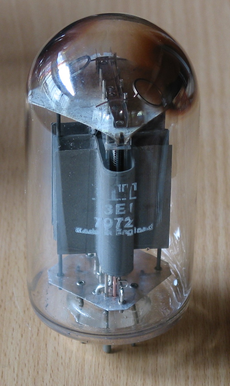
You can see how bad the worst of two worn tubes have become after
years of wonderful music.
There is a reflection of a window on the top left of the picture,
but very nearly all gettering
metal has been used up on the two sides of the tube. You can see
the round gettering rings
which were fitted when the tube was made, and it was from these
rings that the metallic
gettering was sprayed onto the glass internally under a vacuum
during manufacture.
NOTE, Gettering changes shown above can occur in many other tube
types, and one may
see where gettering is "nearly used up" and if the tubes have been
used for 5 years it
is very wise to replace them. And NO, I do not have shares in tube
making companies.
I suggest everyone Google "vacuum tube manufacture" to learn more
about how
tubes are made.
Some images for SE32, 2012.........
Image 4. Two SE32 monoblocs on bench, without covers.
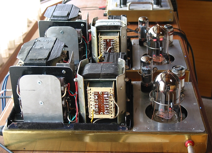
Note capacitor enclosure bottom left. Easy access for setting for
OPT load match on
board on OPT for sec winding terminations.
Image 5. Two monoblocs on bench without covers.
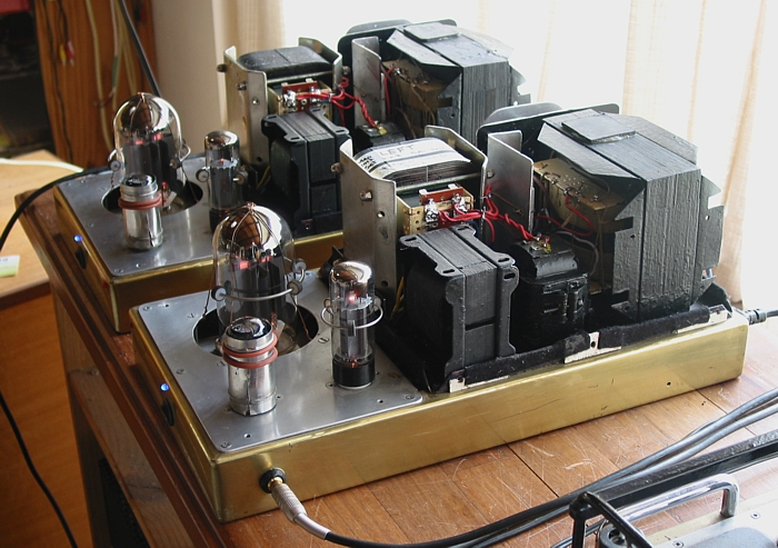
This shows the layout of parts on top of chassis. Fully shielded
tube is 6SL7, with 2 reddish tube
dampers fitted by owner ( which don't do anything IMHO ). EL34 and
13E1 have dampers also
fitted. 13E1 has copper wire used to stop tube falling out of
socket which is possible due to
small socket size and weighty tube.
Iron wound components are OPT, left rear, Big mains PT far right,
anode choke for EL34
at left front, nearest, and 4H B+ filter choke between PT and
anode choke. Small 5VA
tranny for bias+protect circuit is under chassis. The six B+ 470uF
x 400V rated electrolytic caps
are mounted in a case behind the mains PT.
Image 6. Under chassis view.
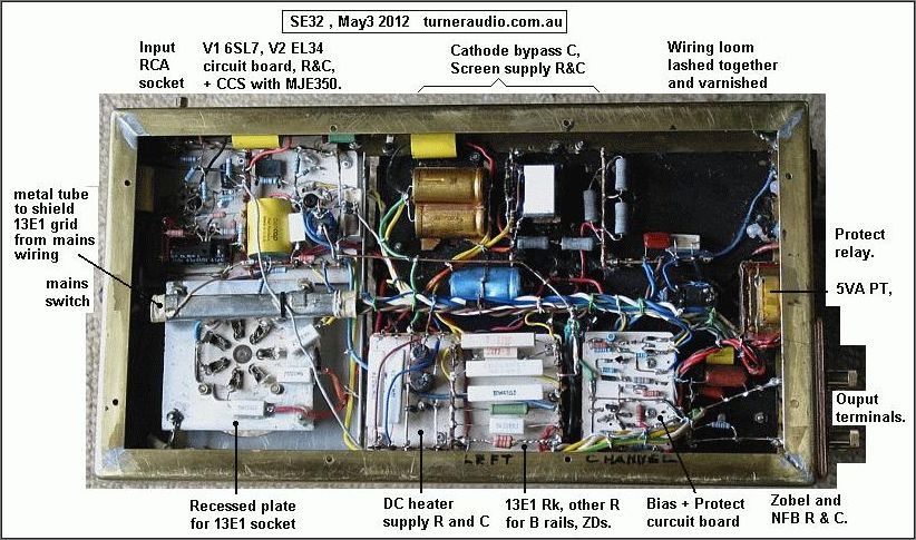
Image 7. Close up bias+protect board.
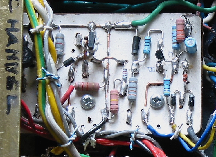
Image 8. Close up 6SL7 and EL34 board. Rather crammed.
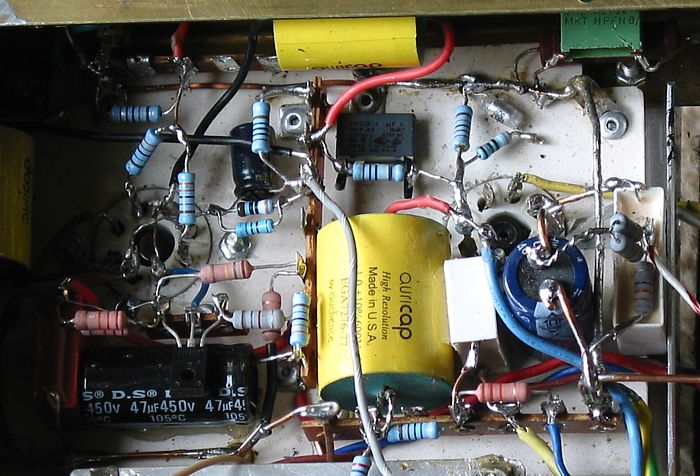
Image 9. SE32, covers on.
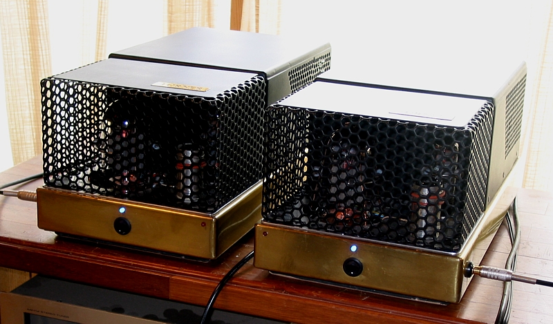
Image 10, May 2012.
Mr Turner has more to say about SE32 amps.....

Happy soldering ! happy swearing ! happy stopping of the
amplifier smoking ! ,and then happy listening! :-)
To
SE32, 2008.
Power amps directory
Index page