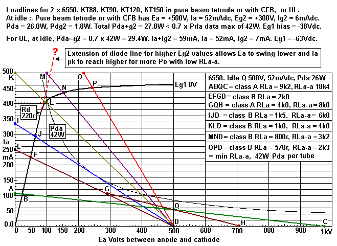
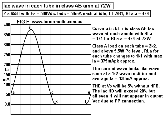
LOAD MATCHING 4C, PP BEAM TETRODES AND PENTODES.
This page 4C follows 4B
This page gives more analysis of loading for PP beam tetrodes or pentodes.
Wave forms in class AB tubes. Notes and calculations for anode dissipation.

In my 5050 integrated amp I used a pair of KT88 for each channel in UL mode. 6550, KT90,
KT120 could be used with the same idle Ea and Iadc conditions with Ea = +500V. I found idle
Iadc = 50mAdc about right for KT88 and it would be for 6550. For the KT90 or KT120 or KT150,
Iadc could be higher in proportion to their maximum Pda rating, if the PSU will not overheat.
But the same 50mAdc could be used all these tubes to give them a long life. The higher Ia may not
change the sound quality, nor the amount of maximum Po. The output tubes operate with 50% UL
taps and each channel can generate up to 72W in class AB1 at anodes. The sound was quite superb.

From the pages load-match 4A and 4B, the meaning of Ra curves and operation is fully described
for each output tube in a PP pair.

Examination of more load lines :-

Fig 1. Loadlines for PP 6550, UL or CFB, class AB1, Ea = Eg2 = +500V for 35% to 50% UL operation.
6550-PPtet-RLaa-9k4-6k0-3k2-2k3.GIF
Fig 1 is based on an abbreviated drawing for 6550 Ra curves for Eg2 = +300V.
Only one Ra curve is shown for Eg1 = 0V, because for loadline analysis there is no huge need to have
all Ra curves for other values of Eg1. The single Ra curve for Eg1 = 0.0V curve is the same where Eg2
= +300V, and suits pure beam tetrode or CFB. There is an extension of the Rd line for higher values of Eg2
or for UL operation.. The exact shape of the Ra curve for Eg1 = 0.0V where Eg2 is up to +450V for
pure beam tetrode is not known.

The diode line resistance Rd = 220r and less than the 125r for GE500A. During countless measurements
of many samples of GE6550A and Russian made 6550, not all seemed to have Rd = 125r.
With UL and CFB, the Rd diode line is usually higher than 125r, as shown in loadlines specifically for UL
below.

The Rd line limits the -Va pk negative going swing. If Rd in your tubes is lower than 220r, you will get slightly
more maximum Po than my loadlines and calculations predict. The knee of the Rd curve begins at 400mA.
But if Eg2 was +440V, the knee would start at above 480mA and enable more power into a lower RL
value without clipping. The resistance value of Rd tends to become lower with higher Eg2, so the Rd line is
steeper and knee is more towards the left. The variations of Rd slope for tetrodes and pentodes do not
need to be known for general design work. Graphed values of Eg1 -Vdc values do not need to be known,
but we all should know grid bias -Vdc will be between -25Vdc and -60Vdc, and the exact Eg1 must be
found by experiment.

With all UL amps, Eg2 = Ea, and the choice of Ea and the UL tap % will determine the height, and shape of
the Ra curve knee, and curves with loadlines are lower down the page.

CALCULATE IDLE DC CURRENT.
For PP class AB1 with 6550, KT88 and all other tubes, and for pure Tetrode or UL, CFB, Triode connections,
the SAFE total idle Pda + Pdg2 should be less than 0.6 x Pda rating in data sheets. For 6550 and KT88,
max rating for Pda is 42W. The Pdg2 is rarely mentioned but can be assumed to be about 10% of whatever Pda
has reached where Ea = Ig2.

To be less confusing, it is best to only use the Pda max figure as a starting point while knowing Pdg2 will be about
10% of whatever idle Pda is selected and where Eg2 = Ea. Where Eg2 is lower than Ea, the Pdg2 will be lower,
and tube will run slightly cooler.

For class A  PP 6550, maximum idle Pda should always be less than 0.7 x rated max Pda, and Ea no higher than
+400Vdc, and Eg2 no higher +300V.

For class AB1, maximum idle Pda should always be less than 0.6 x rated max Pda where Ea is usually higher than
+400V up to about +600V. Pda may be as low as 0.3 x max rated Pda, especially for non hi-fi amps such as guitar
amps where high Po and gross over-driving of output tubes is employed. For 6550, KT88 etc, Eg2 for highest Po
need never exceed about +400V.

LOAD LINES FOR FIG 1. 
For PP pure class A1. Assume enough NFB is used for THD < 1% at 1dB below clipping, for 2 x 6550 or KT88:-
1. Determine Q point. Pda = 0.6 x max Pda = 0.6 x 42W = 25.2W. Calculate Iadc = Idle Pda / Ea
= 25.2W / 500V = 50mAdc.
Eg2 is lower than Ea so Pdg2 will be less than 10% of Pda and Ia can slightly increased to 52mAdc.
 
2. Plot point Q at 500V x 52mA.
3. Plot point B where Ia = twice 52mA and on diode line at 22V x 104mA.
4. Calculate -Vapk swing = Idle Ea - V at B = 22V - 500V = -478V. 
5. Assume +Va pk swing = -Va pk swing. This depends a lot on having enough NFB.
6. Calculate highest Ea where Ia = 0.0mA, = Ea + Vapk swing = 500V + 478V = 978V.
7. Plot point C at 978V x 0.0mA.
8. Draw straight line from C through Q through B and to Ia axis where Ea = 0V.
9. Plot point A at 0V x 105mA.
10. The line ABQC is the loadline for pure class A for each 6550.
11. Calculate the single ended RLa = Va pk swing / idle Iadc = 478V / 52mA = 9,192r.
12. Calculate RLa-a for only pure class A = 2 x SE RLa = 2 x 9,192r = 18,384r.

13. Calculate theoretical SE max class A Po = 0.5 x Iadc squared x RL = 0.5 x 0.052A x 0.052A x 9,192r
= 12.4W.
14. Calculate theoretical max class A1 PP Po = 2 x SE Po for each tube = 24.8W.
15. Note. THD without NFB at class A clipping may be 3%. With enough NFB, THD < 0.5%.

For PP class AB1.
All RLa-a less than 18.4k will allow class AB1 working with maximum Po > 24.8W for max pure class A1.
The initial pure class A1 Po = 0.5 x Iadc squared x lower RLa-a, and is always less than max possible class A Po.
The RLa load while in class A1 = 1/2 RLa-a.
Beyond this amount of initial class A Po, the RLa of each tube becomes 1/4 RLa-a and only for negative going
Va peaks where Ia pk > 2 x Iadc at idle.

EFGD and GQH Loadlines for RLa-a = 8k0.
16. Calculate class B RLa for each 6550 = RLa-a / 4 = 8k0 / 4 = 2k0.
17. Calculate Ea / B RLa = 500V / 2,000r = 250mA.
18. Plot D at Ea = 500V x 0.0mA.
19. Plot E at 0.0V x 250mA.
20. Draw straight line E to D.
21. Plot F at intersection of ED and diode line Rd. F is at 50V x 227mA.
22. Plot G on ED where I = twice Ia at Q, at 300V x 100mA. Vapk swing between G and D = 300V - 500V
= -200V.
23. Plot point H for equal +Vapk swing at 700 where Ia = 0.0mA. H is at 700V x 0.0mA.
24. Draw straight line from G though Q to H. GQH is the class A RLa for each 6550 during initial class A Po.
25. Calculate RLa for class A = Ea change between G and H / Ia change between G and H = 400V / 100mA
= 4k0.
26. Load GQH should be exactly 1/2 RLa-a.
27. Calculate initial pure class A1 = 0.5 x Vapk squared / RLa = 0.5 x 200V x 200V / 4,000r
= 5W for each 6550.
Class AB1 from both tubes = 2 x Po for each tube = 10W.
27. Calculate maximum class AB1 Va pk swing. Ea minimum at maximum peak Ia is at F for 50V x 227mA.
Vapk swing = Ea - V at F = 500V - 50V = 450Vpk. This means there is 318.15Vrms at each anode,
with opposite phase, and Va-a between anodes = 636.3Vrms.
Max class AB1 Po = Va-a squared / RLa-a = 636.3 x 636.3 / 8,000r = 50.6W.

Without load line analysis, max Ia pk for B RLa = Ea / ( B RLa + Rd ) = 500V / ( 2,000r + 220r ) = 0.2252A.

Max class AB Po = [ ( Ia pk for B RLa ) squared ] x RLa-a / 8.0 with Iapk in Amps, and 8.0 is a consant.
For above and for max AB Po = 0.2252 x 0.2252 x 8,000 / 8 = 50.73W.
This agrees with the class AB1 max Po found by load line analysis.

Max class A Po = 0.5 x Iadc for one tube squared x RLa-a = 0.5 x 0.05A x 0.05A x 8,000r = 10.0W, as above.
---------------------------------------------------------------------------------------------------------------
If the Eg2 was say +350V ot +400V, the Fig 1 Rd straight line would continue straight to a higher Ia where the
knee of the Ra curve for EG1 = 0.0V begins. If the higher Eg2 is used, the Va pk swing to a lower Ea minimum
becomes possible and the maximum possible class AB Po would increase.
Po would be found to reach a maximum of about 135W with RLa-a = 2k2. This may over stress 6550 if
continuous Po is desired. The screen Pd g2 may exceed maximum ratings and if the load became a short circuit
the death of 6550 would be fast. Speaker loads change with frequency and a nominal "8r0" speaker may have
impedance variation between 4r0 and 20r within the 80Hz to 800Hz band which carries most of the audio energy.
Assuming the speaker was only 8r0 could cause the amp to overheat.
The user MUST KNOW what the speaker impedance is for all F, ie, he must have the ZL vs F graph before
choosing the OPT outlets to use with that speaker. Getting high Po from tube amps capable of high Po in class
AB1 or AB2 is not the problem for most hi-fi listeners but it is very important for any guitar player using an amp
head plus separate speaker bin.
----------------------------------------------------------------------------------------------------------------
For all class AB amps there is high crossover distortion at low levels if Iadc at idle is too low.
The graph for THD vs Vo will show a peak during first 3W. Medium Po will give medium THD which then increases
proportionally to Vo until clipping when THD begins to rise exponentially when the output sine waves begin to
resemble square waves with increasing odd number H products.

A typical good class AB amp 2 x 6550 should make 0.02% at 2W but only if there is sufficient Iadc at idle, and
there is a sufficient total amount of NFB, either only 20dB GNFB, or with UL plus 14dB GNFB, or with 12dB
local output CFB plus 10dB GNFB.

Summary of calculations without drawing loadlines :-

1. Calculate RLa-a for maximum pure class A1 operation of 2 x beam tetrodes or pentodes,
RLa-a = 1.9 x idle Ea / idle Iadc for 1 tube.
Example, Fig 1, RLa-a = 1.9 x 500V / 52mA = 18,269r.

2. Calculate RLa for maximum pure class A1 of one of the tubes in PP pair, RLa = 0.95 x Ea / Ia
= 0.95 x 500V / 0.052A = 9,134
= 1/2 RLa-a.
These results are close to loadline results. 

3. Calculate maximum class A1 Po, Po = 0.5 x Iadc squared x RLa-a = 0.5 x 0.052A x 0.052A x 18,269r
= 24.7W.

4. Calculate class A1 efficiency = 100% x max class A Po / ( 2 x Ea dc x Ia dc )
= 100% x 24.7 / ( 2 x 500 x 0.052 ) = 47.5% at clipping with GNFB, and at anodes.

5. Calculate RLa-a for class AB1, Rd value must be known. Max Ia pk must be known and located
on the straight portion of Rd line.
RLa-a = 4 ( [ idle Ea / Ia pk ] - Rd )
Example Fig 1, Ia pk on Rd = 410mA at beginning of curve of knee. Rd = 220r.
RLa-a = 4 ( [ 500V / 0.41A ] - 220r ) = 3,998r.

6. Calculate B RLa = 0.25 x RLa-a in 5, = 999.5r.

7. Calculate class AB Po for RLa-a in 5.
Class AB Po = RLa-a x Ia pk squared / 8 = 3,998r x 0.41A x 0.41A / 8 = 672 / 8 = 84W.

8. Calculate RLa-a where Ia pk is NOT on the Rd line and is to right of the beginning of knee of curve and on
Ra curve for Eg1 = 0.0V. The Ra curve for Eg1 = 0V must be inspected to locate any chosen value of Ia pk.
The Ea minimum is read from curve by dropping vertical line to Ea scale.
The Va pk swing = Idle Ea - Ea minimum.
B RLa = Va pk swing / Ia pk.
RLa-a = 4 x B RLa.
Fig 1, Choose Ia pk = 450mA on Ra curve and find Ea minimum = 242V.
Va pk swing = 500V - 242V - 258Vpk.
B RLa = 258V / 0.45A = 573.33r
RLa-a = 4 x 573.33 = 2,293r.

9. Calculate maximum Po for RLa-a in 8,
Class AB1 Po = RLa-a x Ia pk squared / 8 = 2,293 x 0.45 x 0.45 / 8 = 58W.

From Fig 1, and from load lines shown, or by calculations, we get the following list of Va and Po for
Class A1 and Class AB1 :-

Table 1. 2 x 6550, idle Ea +500V, Ia 52mAdc, for loadlines in Fig 4.
Po at anodes does not include Rw loss%.
Load

RLa-a
Ea pk
minV
Ea idle Va pk
Va rms
Va-a rms
Max class
AB1 W
Max class
A1 W
Power quality
DF
THD, IMD
BQC
18k4
22
500
478
338
676
0.0W
24.8W
Good
highest
very low
EFD
8k0
50
500
450
318.2
636.4
50.6W
10.8W
Best
high
low
IJD
6k0
68
500
432
305.5
610.9
62.2W
7.9W
Good
high
medium
KLD
4k0
95
500
405
286.4
572.7
82W
5.4W
Good
medium
high
MND
3k2
153
500
347
245.3
490.7
75.2W
4.3W
Poor
low
too high
OPD
2k3
242
500
258
182.4
364.8
58.0W
3.1W
Disgusting
low
Horrible
For good hi-fi from an AB amp, the nominal RLa-a for 2 tubes should give class AB Po
= twice possible max class A Po and give initial class A Po > 1/3 of maximum possible class A Po.
Therefore we should use RLa-a which gives at least 49.6W class AB, and pure class A > 8.2W. 
Table 1 shows 8k0 would be a good center value RLa-a, and an OPT with primary load 8k0 and selectable
secondary loads of 4r0 and 8r0. Any speakers with nominal Z between 3r0 and 6r0 can be used at 4r0 outlet,
and all speakers above 5r0 can be used at 8r0 outlet.

The 6550 will cope well with RLa-a between 4k0 and 16r0; so speaker load may vary between 1/2 to double
the nominal value.

Consider RLa-a = 8k0. During initial class A Po up to 10.8W, each tube is loaded by RLa = 4k0.
Above 10.8W, Ia in Tube 1 cuts off on positive going Va cycles. Tube 2 has negative going Va wave peaks,
and its RLa = 4k0 up to Ia pk = 2 x idle Iadc. As Tube 1 cuts off, the load in Tube 2 increases beyond
2 x idle Iadc and its load becomes B RLa = 2k0.

In Fig 1, The loadlines for RLa-a 8k0 are described by RLa line EQH for 4k0 for class A, and then line EFGQH
is the AB load which includes the B RLa 2k0 between E and F. There is a sharp bend G where the change of load
occurs. In the real world the tubes have low gm near Ia cut off and increasing gm up to about 600mA.
Therefore the cut off behavior of each tube is gradual and at point G there is a bend, not a sharp angle, and the
AB load line is a curved line, and the harmonic products will consist of mainly 3H and low levels of 5H, 7H etc.
The increase of H products due to load change is called "cross-over distortion". The idle Idc condition allows a
smooth transition at change of load, with none of the high THD occurring at low levels in class B amps or AB
amps with very low idle Idc. Thus a huge amount of highly obnoxious IMD harmonic products are avoided.

Calculating the LOWEST usable RLa-a.
Some old books said that no loadline should ever appear above any part of the the curve for maximum Pda.
This was a cautious approach to avoid tubes overheating at high levels of AB Po, but in fact load lines may be
above the max Pda curve without exceeding max Pda.

Consider B RLa loads in Fig 1.
See line KLD for B RLa = 1k0, for RLa-a = 4k0. This load is for maximum AB anode Po = 82W.
Average input power from PSU = average Ia x idle Ea = 0.63 x Peak Ia x Ea = 0.63 x 405mA x 500V
= 127.6W.
Max anode Po = 82W, and class AB efficiency = 100% x 82W / 127.6W = 62.7%. The idea of tetrode or
pentode anode efficiency is considered without including the increase of Ig2 dc when the anode Po goes higher.
This occurs because the Ig2 ac increases much more when Va pk swings down to say 100V than it tends to
reduce when it swings high to 900V. This overall increase in Ig2 dc comes from the PSU, and nobody can avoid this.
At clipping level power the Ig2 dc may increase from say 5mAdc to 12mAdc, so screen input Po rises to
300V x 0.012A = 3.6W, so anode efficiency is really a few percent less than calculated above.
It became engineering convention to ignore this reality. If the beam tetrode or pentode is connected in triode
the screen then becomes power producing. 50% UL connection gives higher Ig2 idle dc because Eg2 higher and
equal to Ea, Eg2 dc increase at high Po is lower than if Eg2 were fixed at the lower Eg2.
The use of say 20% CFB does allow a fixed Eg2, but there is 20% of anode Va applied between cathode and g2,
so screen Idc increase is lower than for pure beam tetrode. There are limits to screen dissipation and these
MUST NOT be ignored.
The use of CFB minimizes screen heating. I have seen screens which glow bright yellow at high levels of Po.
Sometimes this is due to poor alignment of the helical wound screen wires with grid wires so electrons have the
easiest straight line path between cathode without hitting positively charged screen wires and being absorbed
which raises screen input current.
For calculations here for Pda and efficiency, I will not include the screen.

The efficiency calculation can be affected by the sag of Ea when continuously high class AB Po is generated.
Most amps in 1960 had tube rectifiers, and the primary resistance of the HT winding was deliberately made high
to limit the peak Ia within the diode. Tube diodes like GZ32 and GZ34 or 5U4, etc all have strict limits for peak
currents. If the Ia exceeds the limit set by manufacturer the electrons will "take a short cut" between cathode and
anode and form an arc, ie, a short circuit. this causes mayhem in the tube rectifier which then refuses to rectify,
and the mains fuse or fuse in series with HT winding usually blows. The max peak Ia of diodes can be 0.2Apk.
This limits the value of reservoir C after the diodes. The overall result of using a tube rectifier gives a B+ supply
with high output resistance. In Fig 1, the 2 tubes draw Ia = 104mAdc at idle, but at full class AB Po of 82W the
Ia dc rises to 255mAdc, and if the PSU output resistance = 500r then the B+ sags from +500V to 440Vdc, or
by just more than 10%. This reduces the maximum Po so when testing with a continuous sine wave, you would
NEVER measure 82W at anodes. Modern amplifiers may have voltage doubler type of rectifiers using thick low
resistance windings on PT and use 2 silicon diodes each rated for 6A continuously, and these will charge 235uF
instead of the 22uF used in 1960. The result is a B+ supply with total Rout < 100r, and the B+ does not sag very
much. The Si diodes are rated for 1,000V peak inverse voltage, and will last indefinitely. They will easily handle
the higher peak charge currents for larger C, and easily blow any fuses without fusing themselves. There is no
need to regulate the B+ for anodes but there is good reason to regulate a fixed screen supply but ONLY by shunt
regulator which allows Ig2 dc to double, but which then allows Eg2 to sag easily to prevent tube damage.

Above we calculated that the tubes in Fig 1 will draw 127.6W from PSU at max AB1 Po of 82W to 4k0.
The Pda of both tubes = PSU Po - AF Po = 127.6W - 82W =  45.6W, so Pda for each 6550 = 22.8W.
This is less than the idle Pda of Ea x Iadc = 26W. But the simple calculation is based on a perfect class B amp
with no Pda at idle because idle Iadc = 0.0mA. Where there is already some idle Iadc, Pda will be higher at max
class AB Po, so it is safe to allow +10% so we may say that with each tube at clipping with 4k0,
Pda = 22.8W + 10% = 25W. This is well below the tube rating of 42W so the tubes remain cool when
delivering 82W.

With pure class A RLa-a 18k4, the idle input power from PSU = 2 x 500V x 0.052A = 52W. This remains
constant for class A so when the 6550 make 24W of pure class A, the Pda for both tubes = 26W, and each
tube has Pda = 13W, so they run cooler when producing maximum class A Po continuously. As the load RLa-a
is reduced to 4k0 for class AB1, there is less reduction of tube heat, but little increase for loads up to 4k0.

With RLa-a = 2k3, OPD shows the B RLa = 570r, max peak Ia = 450mA, so PSU input = 141.7W.
AF output Po = 58W. Total Pda = 141.7W - 58W = 83.7W, so Pda heat in each tube = 41.85W, and very
close the tube rating max of 42W. If we add 10% because of the initial Pda at idle, tube heat = 46W, and slightly
too high. Then there is the increase of screen heating so the adding of 10% is certainly justified. The anode
efficiency = 100% x 58W / 141.7W = 40.9%, and this alone should tell you the class AB1 operation is poor.
Music signals may not cause tubes to fail with a low RLa-a if there is no clipping. The average Va level without
clipping for busy music is often -10dB below the clipping level, ie 1/3 maximum Va, so average Po = 1/10 of the
maximum with sine wave clipping. The tubes will survive the experience. But in a guitar amp the player may be
addicted to regularly overdriving the amp to produce what becomes a stream of square waves where Po goes
higher than for un-clipped sine waves and PSU power input much increases and then the screen Ig2 dc much
increases and the Pda would very much exceed 42W and the amp would fail with RLa-a < 4k0.
 
RLa-a < 4k0 will be dangerous.

The effects of over drive on amps can be done using pink noise which resembles music. The noise signal should
be bandwidth limited to 20Hz to 20kHz. Occasional clipping of highest peaks may be seen on a CRO, and
average Po = 1/10 of sine wave Po at clipping.

For hi-fi, it is completely stupid to ignore the effects of using a speaker load much lower than it should be, even
when it can be argued that the amp will survive OK.

There are people who will connect 4r0 speakers to a Quad-II amp with its OPT set for 16r0. The RLa-a for
2 x KT66 becomes 1k0. The maximum output Po is reduced from 20W to 8W, thus clipping will easily occur.
The sound will be terrible, and teenagers could easily cook the amp to death. The THD and IMD will rise to
very high, and damping factor reduces to low. 

In Fig 1, if Eg2 was say +440Vdc, the knee of the Ra curve for Eg1 at 0V would begin higher on Rd than
for Eg2 = +300V. I have shown Rd extending up to an unknown shape because I have never seen a data
sheet which has plotted the Ra curves for Eg2 = 440Vdc for 6550. It seems the tube manufacturers did not
want to encourage anyone to see the complete range possible operation or else too many amp manufacturers
would tempt fate by setting up 6550 at their maximum ratings which would lead to many failures and give the
tubes a bad reputation.

If the 6550 do have Ea = +500V and regulated, and with regulated Eg2 at +400V, I did find I could get
Po = 135W. Just how much Po is available from beam tetrodes such as 6550, KT88 or KT120 is discussed
at my page at loadmatch-5-beam-tetrodes-about.html

Fig 2. Graph for Po vs RLa-a for 2 x 6550 beam tetrode.
graph-6550pp-po-vs-RLa-a.gif
Fig 2 gives the anode output Po you may expect from 2 x 6550 set up as in Fig 1 and Ea = +500V,
Eg2 = +300V, both regulated, Ia = 50mAdc approx per tube and with fixed Eg1 bias. Curve A is
theoretical max anode Po assuming tetrode diode line Rd = 220r, slightly higher than shown on data sheets.

Effects of Winding Resistance.
Let us assume you have an OPT with load ratio 8k0 : 8r0, and its total winding losses are 5%, evenly split
between Pri and Sec windings.
Thus the Pri winding has Rw = 2.5% of 8,000r = 200r, in series with RLa-a, and the sec has Rw = 2.5%
of 8r0 = 0.2r, in series with the Sec load. 
If there is 8r0 connected at Sec then the loading to be transformed at the primary is really 8r0 PLUS RwS
of 0.2r = 8r2.
The OPT ZR = 8,000 / 8r0 = 1,000 : 1, so the load at OPT Pri without considering RWP = 1,000 x 8r2
= 8k2.
Where the 2 x 6550 deliver the first 10W pure class A1, both halves of OPT Pri are equally driven through
the 100r of each 1/2 Pri. The RLa-a ends up being 8k2 + 100r + 100r = 8k4. While the tubes make 10W
with 8k0, with 8k4 the class A Po = 10.5W at tubes. The Po at sec would then become 9.975W with 8r0
Sec load. So exactly what is happening with loadings is complicated, but my graph shows you get about 10W
class A with 8k0 : 8r0 OPT which has 5% Rw losses.

Fig 3. Model for OPT Pri and Sec winding resistances.
OPT-winding-resistance-may-2017.GIF
Possibly, this confuses you more than you were, but you need to consider every wound coil as being a
pure winding with zero copper wire resistance but with a real world R value which always appears in
series with the perfect coil. Then you may consider the loads within windings and additional load of
resistance while considering the OPT as a perfect transformer with zero resistance and perfect magnetic
coupling with zero series leakage inductance loss and zero shunt capacitance losses. It is considered here
with infinite primary inductance shunting the RLa-a. These reactances are considered negligible for
calculations of energy transfer between 20Hz and 20kHz, with most energy between 80Hz to 800Hz.

The class A condition can be simplified to being equal to having a tubed current generator connected to
one primary winding with series RwP = 200r, with the secondary as shown.
It can be proved the total winding resistance looking into the OPT = RwP + ZR x RwS
= 200r + ( 1,000 x 0.2r ) = 400r.
The total Rw losses = 100% x Rw / ( Rw + RLa-a ) = 400r / 8,400r = 4.48%.
This agrees with the calculated results in Fig 3.

Above the class A level, the tubes begin class AB action and each 6550 takes turns at cutting off during
its negative going Ia cycle. Once the Ia cuts off in tube 1, the other tube 2 is the only tube coupled to the load
and the model changes to where you have 1/2 a Pri connected to anode with a 100r series resistance, and
the OPT TR is halved, and load ratio is reduced by 1/4 to nominally 2k0.

The class AB condition can be considered simply with total resistance looking into one side of OPT primary
= Rw 1/2Pri + [ ( ZR / 4 ) x RwS ] = 100r + [ ( 1,000 / 4 ) x 0.2r ] = 150r.
The total Rw losses = 100% x 150r / 2,150r = 7.0%.

Therefore the winding losses change from 4.8% to 7.0% due to change from class A to AB. It would be
mathematically difficult for anyone to accurately calculate total winding losses for any AB Po level or value
of RLa-a between the RLa-a for pure class A and the minimum safe RLa-a of 4k0 for high Po.
Most people using a pair of 6550 as in Fig 1 would find the power for 90% of the music signal is covered
by the initial class A for all RLa-a. So total winding losses for high Po do not need to be considered.

If the nominal RLa-a = 4k0 using a 4r0 sec load, and the amp works in class A, the same total 400r for
Rw will be present, so the RLa-a including total Rw = 4k4. The total winding loss %
= 100% x 400r / 4,400r = 9.09%. The nominal B RLa = 1k0.
The % losses in class AB = 100% x 150r / 1,150r = 13.0%.

Where the fractions of RwP / whole Pri and RwS / Sec are equal, the class AB losses are 1.4 times the
class A losses.

For electric guitar amps, where high Po includes negligible class A Po, the losses will be wholly higher
than for class A.
If RLa-a was nominally 4k0, Po not reach 82W because the real RLa-a becomes 4k4, and you may
get 77W at anodes and the losses are 13% and you will get 67W at sine wave clipping.

In Fig 2, Curve X shows the Po at anodes while  Curve Y shows the Po max at OPT sec, based on
having an OPT of with RLa-a = 8k0 where total winding loss = 5%.

There will be few better OPTs with lower Rw if the OPT has been designed using my methods at
output-trans-PP-calc-3A.html

But there are numerous PP OPTs which waste a lot of Po as heat in windings when used with low
RLa-a. Quad-II OPTs are a classic example.

The conclusion for load matching to beam tetrodes or pentodes :-
Set up tubes with idle Pda+Pdg2 < 0.7 x Pda rating.
The Nominal maximum class AB1 Po for hi-fi should be < total idle Pda, both tubes.
Thus for where total Idle Pda = 2 x 26W, max class AB Po should not exceed 52W.

Table 2. For various tubes.
Some corrections for Po because Ra diode curve has higher R at lower Ea, reducing peak
Va negative swing.
Tube type No 
Max Pda
for
1 tetrode
or pentode,
W
Ea at
idle
Vdc
Iadc at
idle,
1 tube,
mAdc
Pda
Idle
W
RLa-a for max
Pure Class A
1.9 x Eadc / Iadc
for 1 tube.
Po, PP max W
RLa-a Nominal
class AB1
0.8 x Ea / Iadc.
Po, PP max W
RLa-a minimum
class AB1
0.4 x Ea / Iadc
Po, PP max W
6550, KT88
42W
500
50
25
19k0        24W 8k0       50W
4k0       82W
6550, KT88
42W
425
60
25
13k5        24W
5k7       48W
2k8       79W
6550, KT88
42W
350
72
25
9k3          24W
3k9       46W
2k0       76W
KT90
50W
500
60
30
15k8        28W
6k6       56W
3k3       90W
KT90
50W
425
70
30
11k5        28W
4k9       53W
2k5       86W   
KT90
50W
350
86
30
7k7          28W
3k3       50W 
1k7       82W
KT120
60W
500
72
36
13k2        34W
5k6       66W
2k8       92W
KT120
60W
425
85
36
9k5          33W
4k0       63W
2k0       84W
KT120
60W
350
102
36
6k5          32W
2k8       60W
1k4       80W
EL34, 6CA7
6L6GC, KT66
27W
425
40
17
20k0        16W
8k5       30W
4k2       45W
EL34, 6CA7
6L6GC, KT66
27W
390 44
17
17k7        14W
7k1       29W
3k5       44W
EL34, 6CA7
6L6GC, KT66
27W
350
49
17
13k6        13W
5k7       28W
2k9       43W
EL84, 6V6
12W
300
27
8
21k0      7.7W
8k9       15W
4k5       19W
EL84, 6V6
12W
250
32
8
15k0      7.6W
6k3       14W
3k2       17W
6CM5
20W
350
42
15
15k8      14W
6k7       27W
3k4       40W
For 2 x 6550, Ea 500Vdc, Ia 50mA each, Nominal RLa-a = 8k0.
OPT should provide 3 load ratios, 8k0 : 4r0, 8r0, 16r0.
For 4r0 outlet, Nominal speaker Z = 3r0 to 6r0,
For 8r0 outlet, Nominal speaker Z = 6r0 to 12r0,
For 16r0 outlet, Nominal speaker Z = 12r0 to 24r0. 
It is impossible to get only pure class A for 4r0 unless an additional output load match for 2r0 is provided.
Then 4r0 speaker used at 2r0 gives RLa-a 16k0, for nearly all class A.
For pure class A for 8r0 speaker, connect to 4r0 outlet.
For pure class A for 16r0 speaker, connect to 8r0 outlet.
--------------------------------------------------------------------------------------------------------------------------
Fig 4. Waves for Iac in class A PP amps.
Waveforms-classA-SE-Ia.gif
Fig 4 shows the current waves for class A in a single tube which can be monitored with a current
sensing 10r0 x 5W between cathode and 0V, with fixed Eg1 bias Vdc applied, and with CRO set for DC,
and for class A operation where theoretical +/- Iadc peaks are equal.
But in practice, the +Iac peaks are more than -Iac peaks, so the average Ia is higher than the idle Iadc
and in fact the single tube draws more slightly more Idc from PSU. 20dB NFB would reduce the 2H
by factor = 0.1, and an inverted 2H signal version of FIG B is included in grid input to output tube which
then is forced to produce nearly equal + and - Iac peaks, so THD in output load is less. The inverted 2H
signal is usually known as the "error signal", ie, the THD found in signal applied to output tube grids.

In a PP circuit, the 2H in current of each tube is not eliminated and allowed to remain, because the 2H
current in each tube has the same phase at each end of OPT primary winding with CT at 0Vac. So the
2H Vac does not appear at OPT sec, so there is no
correction signal generated to force the output tubes to generate equal +Iac peaks and -Iac peaks.
Thus +Iac peaks may be 8 times the idle Iadc, and the Idc supplied to each tube is allowed to increase,
and the 20dB NFB remains effective in reducing THD by a factor of 0.1.

For pure class A operation of any SE power tube, cathode biasing with R + C is used very often
because the Idc supply to tube is regulated by the R between cathode and 0V. As Ek rises, the difference
between Ek and the bias Vdc, usually 0V, increases, tending to bias the grid more negatively, and oppose
Idc increase due to rectifying effects. Cathode biasing is also used in class A PP if the amount of class A
Po with a sine wave at clipping is no more than twice the maximum possible class A. Music signals with
low average Po levels less than 1/10 the maximum AB1 clipping level will not cause much change to Ek.
Many PP amps ( such as Leak ) will have high THD when tested with a sine wave at clipping because PP
amps have no means of using the applied NFB to regulate the Idc. But if tested at 1/4 the clipping Po, ie,
with 1/2 the maximum possible Va-a, the rise in Ek is not more than with a SE class A tube.

With cathode biasing, you MUST remember idle Ea is the Vdc between anode and cathode. B+ at CT
= Ea + the Ek, and the HT secondary must allow for the increased B+ where cathode bias is used.
The Eg2 is also between g2 and cathode, so the Vdc between g2 and 0V must be increased above the
case with fixed Eg1 -Vdc bias with cathodes at 0V.

Fig 5. Theoretical anode Iac waves in class AB1 with RLa-a = 8k7.
Waveforms-Ia-classAB-RLaa-8k7.gif

Fig 5a. Real anode Iac waves in class AB with RLa-a = 8k7.
Waveforms-Ia-classAB-figE-RLaa-8k7.GIF

Fig 6. Anode Iac waves in class AB with RLa-a 4k4.
Waveforms-Ia-classAB-RLaa-4k4.gif
The wave forms show that most class AB amps with low RLa-a loads do not work much
differently to class B amps at high levels, and for best hi-fi, The initial amount of pure class A
should be about 1/3 of maximum possible Class AB1.
-----------------------------------------------------------------------------------------------------
I have enormous reluctance to use Ea higher than :-
+500Vdc for any octal tubes such as KT88, 6550, KT90, KT120, 13E1.
+450Vdc for EL34, 6L6GC, 807, KT66, 5881.
+330Vdc for EL84, 6V6, 6CM5, 6GW8.
+250V for EL86, 6BM8, EL95.
+1,000V for 813, 845, 211, GM70.
For pure beam tetrodes and pentodes, or use with CFB, Eg2 lower than Ea generates less
THD than if Eg2 = Ea when Ea is above about 300V.
------------------------------------------------------------------------------------------------------
The Eg2 will be equal to Ea in UL mode or triode, and Pdg2 is lower in these modes.
For pure beam tetrode or pentode mode, peak Ig2 occurs when Va swings low and Ia is high, but the
large increase in electrons flowing to anode past the screen which may be hundreds of volts more positive,
so the Ig2 increases. In UL or triode, the g2 swings low with anode, thus not attracting so many electrons.

We should think about 6CM5, 6DQ6 13E1 and other beam tetrodes invented after WW2 as being less
flexible with Eg2 than other tubes such as EL34, 6L6GC, 6550, KT88 etc. 6CM5 must not be used in
triode or UL mode with Ea > +375V because the grid bias needed must be very negative to get the
wanted Iadc. 6CM5 are quite happy with Eg2 = 200Vdc, and Ea may then be 400V+, with Eg1 bias less
 than -50Vdc. If idle Eg1 is too negative, say more than -60Vdc, there is less chance the idle Iadc
The same limits for Ea and Eg2 apply to 13E1. I will suggest both tubes work best with 20%  CFB
windings and fixed Eg2 at 250Vdc, and Ea < 450V, to get low THD and low effective Ra. These and a
few other tubes developed in 1960s were designed to work with low Eg2. They tend to have higher g2 gm
which makes UL or triode connection give lower effective Ra than with EL34 or 6550. Triodes such as
300B, 845 are quite happy with up to -100Vdc or -190Vdc bias Eg1.

For real triodes, Ea should not exceed :-
+300Vdc for 2A3,
+450Vdc for 300B,
+1,200Vdc for 845, 211, 805, GM70.
--------------------------------------------------------------------------------------------------
MORE ABOUT ANODE HEAT IN OUTPUT TUBES.
Whenever the tubes operate in pure class A1, the anode dissipation will never be higher than the idle Pda
= Ea x Iadc.
During class A operation, tube Pda reduces to a minimum of of about 0.55 x Pda at maximum class A Po.

With tetrodes and pentodes in pure class A the anode efficiency is highest at about 46% so that if there
are two 6550 with total Pda = 50W, then Maximum pure class A power = 23W. At this maximum Class A,
Pda per tube = 13.5W. For hi-fi the average PO level is rarely above 1/10 of the maximum possible PO,
so Pda is always nearly constant and temperature is stable unless there is a load which is too low.

But with class AB where the amount of possible initial class A power is less than 1/3 of the total AB
power possible for the load value, the Pda will always rise slightly after the first few watts are produced.
Fig 7. Formula for calculating Class AB Pda :-
Formula-Class-AB-Pda-calc.GIF
This dreadful formula is a trap for those not able accurately use to calculations.
Pardon the use of a .gif but it is easy to read, and may even be seen on a smart
phone screen.
But please be a REAL MAN, and use a PC or laptop with a 15.6"
( 390mm diagonal distance across screen ) - at least, to read this website properly.
A pocket is needed and you may carefully copy out the formula on paper so that you can insert your
figures for the 20 other types of output tubes you may want to use instead of 6550. The use of such
formulas has very high risk of a DUMB MISTAKE, and you get a crazy answer that just could not be
true.

This formula here took time to generate because I could not find any formula anywhere which could
calculate Pda for CLASS AB amps with fairly high Idc at idle which included the effect of the idle biasing.
In effect, class AB tubes that run hot at idle will run even hotter at higher Po, and we need to find out just
how hot they will get. The formulas I did find considered class AB amps as if they were biased for class B
with zero Idc at idle.

If idle Iadc = 0.0mAdc, major parts of the formula disappear, and Pda = ( Ea x 1.8 x Va-a / RLa-a ) - Po. 
The part ( Ea x 1.8 x Va-a ) / RLa-a is DC Power from PSU. It is another way of saying PSU power to
anodes = Ea x 0.63 x Iapk for B RLa.
So for class B, my formula gives Pda = ( 500 x 1.8 x 362 / 2,300 ) - 57 = 141.6 - 57 = 84.6W
so Pda per tube = 42W.
My previous formula above :- Pda = ( Ea x 0.63 x Ia pk B RLa ) - Po, and will give the same answer. 

My complex formula will give best results for ANY bias level of operation and for low ratio between Ia at
idle and peak Ia for class AB.

Here is my formula again, but in text :-
Pda =
Ea x [ ( 0.364 x Iadc ) + ( 1.8 x Va-a / RLa-a ) + ( 0.364 x Iadc squared / { ( 2.83 x Va-a / RLa-a ) - Iadc } ) ] W - Po.
Where 0.364, 1.8, 2.83 are constants for all equations. Iadc = Idc at idle, one output tube of a pair,
Va-a = Vrms anode to anode across RLa-a, also = ( 1.414 x Va Pk swing at one anode ),
and RLa-a = load across CT primary of OPT between two anodes, also = 4 x B RLa for each tube.

Let me calculate for RLa-a = 2k3, because above, I did calculate this load to be the one where Pda in each tube
would reach the Pda limit = 42W at sine wave clipping, for 6550.
For RLa-a 3k3, Po = 57W, Va-a = 362Vrms, Ea = 500V, Ia at idle = 0.05Adc.
Pda for both tubes =
500V x [ ( 0.364 x 0.05A ) + ( 1.8 x 362V /  2,300r ) + ( 0.364 x 0.05A x 0.05A / { ( 2.83 x 362V / 2,300r ) - 0.05A } ) ] W - 57W  
= 500 x [ 0.0182 + 0.283 + 0.0023 ] W - 57W
= 151.75W - 57W = 94.75W. Pda per tube = 47.4W, and above what the simple calculation above gave.
My equation is based on Pda of 2 tubes = PSU DC input power - Audio frequency output power.

The anode efficiency can also be calculated as 100% x Po / PSU power = 100% x 57W / 151.7W = 37.5%.
In a perfect class B amp, maximum efficiency = 78%, and for 57W output, you would need only 73W
for DC power from PSU.
This is never seen in any amp because devices cannot turn on fully to become equal to a switch with resistance
< 1r0. The diode line Ra curve always limits negative going Va swing, even when class AB2 is used.
A tube is not like a power mosfet which has "on resistance" between 1r0 and 2r0.

Class B amps will have surprisingly low Pda in devices at maximum Po and at zero Po but at 2/3 maximum
Po the devices have higher and lower efficiency than at clipping levels. Maximum efficiency in class B tube amps
is about 67%. Where efficiency is less than 50% at clipping, it is unlikely there will be higher Pda at less than
clipping levels.

Calculate Pda at 0.67 x maximum class AB Po for 2k3 = 0.67 x 57 = 38.19W. Va-a = 296Vrms.

Pda =
500 x [ ( 0.364 x 0.05 ) + ( 1.8 x 296 / 2,300 ) + ( 0.364 x 0.05 x 0.05 / { ( 2.83 x 296 / 2,300 ) - 0.05 ) } ) ] W - 38W

= 500 x [ 0.0182 + 0.232 + 0.00289 ] W - 38W
= 126.5W - 38W = 88.5W. Pda per tube = 44.27W. The Pda is slightly less than at clipping, but it is
still above Pda rating for tube.
 
With RLa-a = 1k8, I calculated clipping Po max = 45W and Pda per tube = 54.6W.

The minimum load for 2 x 6550 in class AB with Ea = 500V should not ever be less than 3k5.

Instead of 2 x 6550, you can use use 4 x 6L6GC, KT66, EL34 and with Ea = +450Vdc max, and Eg2 at the
same +300Vdc. The same rule applies for class AB1 with Pda at idle = 0.6 x Pda rating. For EL34 with 28W rating,
Pda at idle = 17W, and the 4 tubes have Pda = 68W, and the possible class A = 30W, more than for
2 x 6550 and the anode load can be lower than for 6550. I have never ever met anyone needing more than
4 x EL34, although many said they wanted more.
------------------------------------------------------------------------------------------------------------------------------

Tables 3 to 5 for wanted load match possibilities with 3 different load strappings, with max class AB1
and class A Po at speaker, allowing for total Rw loss%.

Table 3. Nominal OPT for 8k0 primary, strapped for 4r0 sec load.
XX brand name
Speaker
Nominal Z
RLa-a
OPT ZR
2,000 : 1
TR = 44.72
Max class AB1 Po
at OPT sec,
Watts. 
Max class A Po
at OPT sec,
Watts.
OPT winding
loss %
( approx ! )
THD
2r0
4k0
72W 5.0W
15%
high
3r0
6k0
56W
7.5W
10%
high
4r0
8k0
47W
10.0W 7%
med
6r0
12k0
33W
15.0W
5%
low
8r0
16k0
27W
20.0W
3.0%
low
12r0
24k0
nil
18.0W 2.0%
low

Table 4. Nominal OPT for 8k0 primary, strapped for 8r0 sec load.
XX brand name
Speaker
Nominal Z
RLa-a
OPT ZR
1,000 : 1
TR = 31.62
Max class AB1 Po
at OPT sec,
Watts. 
Max class A Po
at OPT sec,
Watts.
OPT winding
loss %
( approx ! )
THD
4r0
4k0
72W 5.0W
15%
high
6r0
6k0
56W
7.5W
10%
high
8r0
8k0
47W
10.0W 7%
med
12r0
12k0
33W
15.0W
5%
low
16r0
16k0
27W
20.0W
3.0%
low
24r0
24k0
nil
18.0W 2.0%
low

Table 5. Nominal OPT for 8k0 primary, strapped for 16r0 sec load.
XX brand name
Speaker
Nominal Z
RLa-a
OPT ZR
500 : 1
TR = 22.37
Max class AB1 Po
at OPT sec,
Watts. 
Max class A Po
at OPT sec,
Watts.
OPT winding
loss %
( approx ! )
THD
8r0
4k0
72W 5.0W
15%
high
12r0
6k0
56W
7.5W
10%
high
16r0
8k0
47W
10.0W 7%
med
24r0
12k0
33W
15.0W
5%
low
32r0
16k0
27W
20.0W
3.0%
low
48r0
24k0
nil
18.0W 2.0%
low

Fig 7 shows curves for a 6550 with 43% UL taps. The drawing is an accurate copy from data sheets,
with Ea taken up to 800V to get a slightly better idea of what happens at high Ea swings where Ea > 400Vdc.
The Ra curves are more regular than pure beam tetrode, and the diode line is not straight, but is an average
of about 250r. Idle point is for Pda = 25W, Ea = 500V, Ia = 50mAdc. The grid bias EG1 will be at about -64Vdc.
This is because Eg2 = Ea = 500Vdc.
The knee of the curve is vague, but I have plotted IJC = B RLa = 1k0 for 4k0 minimum RLa-a. Max AB Po = 76W,
Class A Po = 5W.
 
The line DEHC is for B RLa = 2k0 and for RLa-a = 8k0. Max AB Po = 53W, Class A Po = 10W.
FHQG is the 4k0 class A load for each tube while working in initial class A.
The RLa-a load for only pure class A is NOT shown but will be 18k0 approx, giving class A Po = 22.5W.

OPT-1A will work just fine in UL mode with a pair of 6550, KT88, etc.

Fig 8. Blank sheet for drawing 6550 UL load lines.
6550-ultralinear-blank-43%25-curves.GIF
Fig 9. Blank sheet for drawing 6550 triode load lines. Notice that the diode line resistance
value between 0.0mA and 300mA = 235r.

6550eh-triode-Ea-Ia-curves.gif
Here are triode Ra curves for 6550 so you may compare the Ra values for different Ea and Ia
points by drawing parallel straight line to the Ra curve near Ea and Ia point. The Ra at point
= straight line V change / I change.

Composite Load lines.
The loadlines in text books for PP output tubes are most confusing and difficult to draw. In RDH4, pages
574 and 575 have two sets of triode PP Ra curves drawn with one set inverted and the two above and
below a center horizontal line. Page 583 has the similar "composite" sets of Ra curved for 6L6, and all
this seems all so smart looking, but it is bamboozling, and what we need to know is just exactly what
happens in ONE of either tubes in a PP circuit. Anyone reading RDH4 in 1960 would need to make
two paper copies of Ea vs Ia characteristics then use scissors to trim off below the Ea axis below 0.0mA,
 then place one copy upside down below the other. The process would involve tracing paper over data
curves, drawing 2 curve copies, and juggling paper for a day. I doubt if anyone who did not work in RCA's
head office ever drew composite PP load line curves. Page 583 says there is no need where you just want
to know class AB Po and Class A Po, and what Ia peak may be with low loads to estimate the lowest
safe load for any two tubes, ie, what I am tying to tell you here. MSPaint on a PC screen will allow
composite curves to be produced easily, but I see no need.

More about tubes other than 6550.
For EL34 or 6L6GC with Pda rating of 25W, and in a typical guitar amp with Ea + Eg2 = +450V,
idle Pda = 0.6 x 25W = 15.0W. Iadc = 15W / 450V = 33.0mA. The Ig2 may be 3 to 5 mAdc.
There is no need for any higher idle and I have set Ia = 27mA in many amps which tended to make the tubes
last longer. This amount of idle Idc is enough to reduce crossover distortion which is benign in guitar amps
which form part of the instrument by adding harmonic content that is good sounding providing it is mainly
2H and 3H well before the amp clips. Guitar amps usually have about 8dB global NFB to slightly reduce
the Rout and slightly reduce THD and to allow a brightness control which reduces the NFB above 2kHz,
and boosts the HF by +6dB.

The anode RLa-a load for guitar amps is usually 1/2 what is used for a hi-fi amp. But the same rules for safe
operation apply to both types of amps. 

Some EL34 or 6L6GC in guitar amps with Ea less than 400V have been intended to give mainly class A for
small venues where the output tubes are never over-driven and the distortion is deliberately created by
overdriving the 12AX7 input stages. The rules for class A output stages are the same for guitar amps or hi-fi amps.
Class A requires RLa-a loads that are twice those for the mainly class B loading of high Po guitar amps where
it is common tom have 4 x EL34 or 6L6GC produce 100W.

Some smaller cheaper tubes like 6BQ5 / EL84 or 6V6 can also be idled at Pda 10W for Ea = +300V,
with their Pda rating = 12W. I prefer idle condition = 8W each.

For 6550, KT88, idle Ea = 500V, idle Pda +Pdg2 = 0.6 x 42W = 25W. Thus idle Ia = 25W / 500V = 50mAdc.
 If Pdg2 is 10% of Pda, then Pdg2 = 2.5W. For where Ea = Eg2 = 500V, the Ig2 may be 5mAdc.
If Eg2 is lower at say +300Vm expect Iadc to be lower. 

Ea rating for 6550 or KT88 is well above +500V, which I have often used. I have nominated Eg2 at +300Vdc,
giving Pdg2 lower than Eg2 ratings. Old UK made KT88 had higher Eg2 rating than 6550 but only an idiot
would ever use Russian or Chinese made KT88 with Eg2 based on old MOV KT88 ratings. These new 6550
and KT88 have exactly the same internal structures and should be treated as equals. Their names vary for
marketing reasons only. NEVER use Eg2 higher than 450V for 6550, KT88, KT90, KT120, or KT150.

But in UL amps the Eg2 = Ea and nobody can avoid having Eg2 above +450V if Ea = +500V. However, this is
OK for UL taps to be between 30% and 50% of the anode Vac because where there is a large fraction of
anode Vac applied to screens the screen Pda does not increase to dangerous levels as it does with a fixed high
Eg2 supply. Old 807 or 6L6 had Eg2 rating of 300Vdc max, and you would not dare to exceed this. Pa amps
were made with Ea = +600V and Eg2 = +300V and you could get 80W from a pair using class AB2. THD
without NFB > 13%. Similarly , 96W was possible from 2 x EL34 with Ea = +880V and Eg2 = +450V.
The idle Ia would be 12mAdc, and RLa-a for mainly class B was about 11k0. These types of amps had a
history of unreliable operation. Use more tubes if you want high Po, and do not flog a single pair to death.

HISTORICAL REASONS FOR CLASS AB.
The reasons for class AB were found soon after triodes were invented before 1920. A single triode might make
5W in SET class A. If you paralleled a pair you got 10W in SET. But if the same 2 triodes were connected in
push-pull to an OPT with a primary with CT, The Idc could be reduced to maybe 1/4 of level used for class A,
and Ea could be raised, and the pair of tubes could produce up to 20W in near class B operation. Even more
was possible with class B2, or class C for RF amps. However, for hi-fi, everyone knew class A was best, and
if you got 10W from a pair of triodes in class A, it would be be clean enough for the most critical ears.
The radio transmitters, radio tuners and speakers of 1925 all generated large amounts of THD / IMD and it
was pointless being too fussy about your amp. But by 1950, the LP and FM radio and tape recording arrived
and then everyone expected amps to be a lot better than 1925 standards, and Mr D.T.N Williamson set the
standard that remains good today with his 16W amp with 2 x KT66 in PP AB triode.
Tubes were expensive, but there were plenty of 6V6, 6L6, KT66, 807 available and all make good triodes
when screens were connected to anode. It was found that if the idle current was less than for pure class A,
then class AB could offer 16W AB and with first 8W in class A and this pleased most ppl. But then the UL
connection became popular and only needed 2 taps on OPT primary and without any other change there was
32W available. Quad-II used CFB windings, but had Ea and Eg2 at about 350V, so 2 x KT66 were limited to
about 22W and although the Quad OPT was well designed, its winding losses were higher than many other amps
and by the time it may have been a great idea to make a much better amp with CFB, aka Acoustical,
Quad switched to solid state.
Almost nobody could tell the difference in sound quality between PP triodes or UL, or CFB where it was used.
If you had a quad of KT66 in triode to make 32W in PP pure class A, the sound was no better than if you had a
pair in UL class AB able to make the same 32W. I have heard so many happy customers tell me they like their
class AB amp.

But the aim of class AB should never be to make the highest possible level of sound, but to provide accurate
sound free of any blemish. The exception to this hi-fi rule is found in all musicians amps where are pair of 6L6GC
have Ea = Eg2 = 450Vdc, and you force the two tubes to make 50W in near pure class B, and then over drive
them for a bit more in class C. It is not hi-fi, and the amp is part of the guitar, and "anything goes" and the aim
is to exploit the tubes harmonic generation which is found to be better sounding than anything done with solid
state which most musicians say lack the warmth of sound in tubes.

In the world of hi-fi listening, the power amps never go near clipping and average power levels for each speaker
are 0.5W. Class AB has high enough maximum Po to avoid clipping on peaks in music signals while having
enough initial pure Class for most of the music signal. If a speaker makes 88dB/1.0W/1.0M, then you need 0.5W
for 85dB SPL, 5W for 95dB, 50W for 105W.
100W gives 108dB SPL. This would be in an anechoic chamber but in an average room the levels at 1M may be
3dB higher. But you sit at say 3M from speakers and levels will seem similar to 1M in the anechoic chamber.
With two speakers and two amps, 50W from each will be enough to reach 108dB.
But for average busy levels of stereo, at average SPL 85dB, 0.25W is average amp power. Many ppl get by on
much less than  50W per amp with say 2 x 6550, but the 50W amp will make much less THD and IMD at
0.5W than something capable of only 10W using 2 x 6BQ5.
Many hi-fi enthusiasts over age 40 do not like loud music; they just want accuracy they hear when they attend a
concert without any "sound reinforcement" with damned amps and speakers.
A pair of EL84 can give you hi-fi but speaker sensitivity should be at least 94dB/W/M, and as soon as you try
low sensitivity then the shortcomings become apparent. Many speakers made in 1960s did have such high
sensitivity at 1kHz, but definitely not at 40Hz. Many modern speakers have much lower sensitivity but it extends
to low bass frequencies. If you have doubts about having only 2 x EL34 or 2 x 6550 per channel, then a quad
of these tubes to end all doubt.

Back to
loadmatch-4A-PP-tetrodes-pentodes.html

loadmatch-4B-PP-tetrodes-pentodes.html

Forward to
loadmatch-5-beam-tetrodes-about.html

To
index.html