Wien bridge oscillator with tubes.
Last update of this page, 26 March 2015.
The only schematic difference to earlier versions of this page is
for better HF stability in amp in Fig 2,
by adding S1c, and C4a, 2n7, etc. Please use the Fig 2 schematic
as I have it if you copy the design.
Just remember, if you make smallest change to anything I have
done, it may result in degraded performance.
Be prepared to solve all your own problems.
Many past sine wave oscillators with tubes had insufficient
bandwidth with high THD.
Here are details of two I built which were much better than
Hewlett-Packard's 1930s first Wien bridge
AF oscillator that gave 30Hz to 30kHz.
Many old variable F tubed oscillators used LC circuits which are
not covered in this page.
I have used tubes to produce the sine waves with both Wien bridge
oscillators here. I begin with a
re-engineered 1950s AWA telephone tech oscillator for sine waves
only from 1Hz to 220kHz.
The second has tubes to make sine waves from 1Hz to 2.2MHz. It has
a solid state Schmitt Trigger
circuit to convert sine waves to square waves, and has a solid
state output buffer and multi level
switched output attenuator. Overall performance is far better than
many units using common audio
op-amps.
Picture 1. Re-engineered 1955 AWA oscillator.
Fig 1. Schematic WB tubed oscillator, 2005. 1Hz to 220kHz.
Table 1. Measured R values for WB RC network.
Sheet 1. Schematic, WB tubed oscillator, Sheet 1, amp, 1Hz
to 2MHz 2013.
Sheet 2. Schematic, buffer output for WB tubed oscillator,
Sheet 2.
Sheet 3. Schematic, Schmitt trigger and amp for WB tubed
oscillator, Sheet 3.
Graph 1. Square wave harmonic content.
Sheet 4. Schematic, Power supply for WB tubed oscillator,
Sheet 4.
Fig 2. Small signal bjt discrete bjt op-amp.
Picture 1. Old AWA oscillator sold to PMG ( Govt post and
telephone company ) from 1950s.
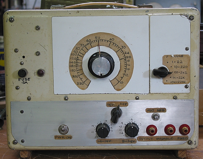
In around 1995 I was given a tubed Wien bridge oscillator made by
AWA Australia for telephone
technicians. Like many ancient oscillators made after about 1933
there were only 3 frequency ranges;
this one 20-200Hz, 200-2kHz and 2kHz-20kHz. The original AWA unit
used a dual gang AM radio
radio tuning cap to vary F by switching 3 pairs of resistors with
highest R value = 22M, lowest value
220k.
It was very inadequate test gear for testing hi-fi amplifier
amplifier response needing examination between
1Hz and 220kHz at least. I recall it had a 6SL7 and 6SN7 used as
output tube driving 20k : 600r OPT
which I still have for odd purposes.
I completely re-built the unit........
Fig 1. Reformed 1955 PMG AF oscillator.
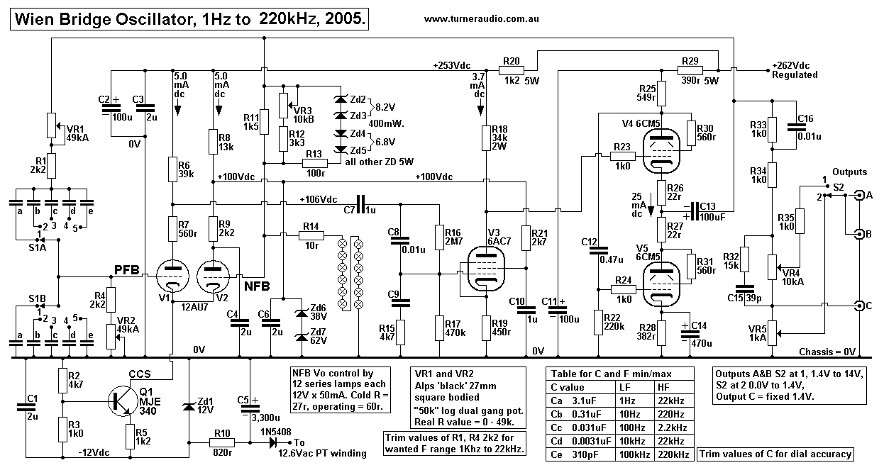
There are 5 frequency ranges, 1Hz-22Hz, 10Hz-220Hz, 100Hz-2.2kHz,
1kHz-22kHz, 10kHz-220kHz.
F control uses available Alps dual gang log 50k "Black" pot with
27mm square body to alter the F.
There are 5 pairs of fixed capacitors switched by 2 pole x 6
position old wafer switch. One position is wasted.
The Alps pot has well matched tracks with continuous wiper contact
so that wave form amplitude "bounce" is
minimized. I found each track measured 48.2k max.
With the added series R of 2k2, max R = 50.4k, min R = 2k2, and at
centre rotation ( dial = 12 o'clock ),
total R = 11.14k, and pot R = 8.94k which is 0.18 x max pot R.
Some "log pots" produce -20dB attenuation from wiper at the centre
position or"12 o'clock" position, ie,
there is 10:1 signal voltage reduction at centre position. AFAIK
this is regarded as a true log pot but
depends on source signal R < 100 x total track R, and assumes
the loading of wiper output > 10 x track R.
A true log pot of 50k driven by a cathode follower and for gain
pot to a preamp grid and set at centre has
5k from wiper to 0V and 45k from wiper to source. ( The output
resistance from wiper = 5k // 45k = 4k5 ).
Many so called log pots including the Alps I have used have a
voltage step down ratio of approximately 5:1.
The "50k" Alps pot I used had track R = 49.6k and between wiper
and 0V track was 8.9k when in centre
position.
WB oscillators using pots generally have one end of track
connected to the wiper to make a simple variable R.
The Alps gave me a pot range 49k to 0k0. There is a series R1+R4 =
2k2 each so that each R in Wien RC
network is varied between 52.2k max to 2k2 min. This allows F
variation between 10 and 220.
At near centre of rotation R = 11.1k and F = 50. F between 10 and
50 fill 1.2 the dial and numbers 50 to 220
fill the other half so numbers are spread out to allow easy
reading to at least 2 significant figures keeping reading
errors less than +/-2%. The dial readings have been verified by
measurement of R in Table 1 below.
With the Alps pot I used, and with a series 2k2 I measured the
total R values :-
Table 1. Measured R values with dial pointer set to
calibrated dial numbers.
Hz
|
10
|
12
|
14
|
16
|
20
|
30
|
40
|
50
|
60
|
70
|
80
|
100
|
120
|
140
|
200
|
220
|
R total
k ohms
|
50.4
|
41.7
|
35.5
|
32.0
|
24.6
|
16.4
|
12.6
|
10.0
|
8.29
|
7.03
|
6.11
|
4.80
|
3.94
|
3.44
|
2.48
|
2.25
|
The "50k" pot plus 2k2 gives variation slightly more than max and
min values of table so the real F range
is from about 9.8 to 223 and allows for trimming C values.
The pot for a Wien bridge oscillator needs to have a smooth R
change giving centre position attenuation
ratio of between 4:1 and 10:1.
This applies where you want each F range to be a decade of F, say
10Hz to 100Hz.
Do not try to use a linear pot. There is no way to add additional
R to make a "quasi log" pot for this application.
I tried, nothing works. If a linear pot is used for a decade of F
between 10 and 100, then centre position gives
18.1, and numbers between 18 and 100 become very crammed and the
high end of dial.
Few cheap dual gang "log pots" give a smooth R change vs rotation.
The $4 types from Jaycar are mostly not
worth buying for a WB oscillator. Some seem linear for part of the
turn, then suddenly change to a lesser R,
and maybe again, so the pot does horrible things to how the dial
numbers appear. The two tracks are often
poorly matched and added trimming R do not much improve the pot
function, and it becomes impossible
to get a flat response for all F in all bands.
Cheap pots are unsealed, allowing pollution, dust, and soldering
fumes to settle on tracks pots tend to have
loosely riveted track connections.
If you must use such crap, spray insides with WD40, press up
rivets more tightly with long nose pliers, seal
around open holes with cardboard and silicone before soldering.
Take your Fluke DMM to the shop and
sort through their bin for the best match of tracks and obtain the
highest ratio for track R for each side
of the track with wiper set to centre position. Seek the "most
logarithmic" with highest attenuation ratio
at centre you can find. And don't be surprised when you find they
ain't very good when you use them.
I tested an ancient dual gang 5.0k Colvern wire wound pot formerly
used in WB oscillator.
These were very well made with precise matching and smooth R
change. But they suffer from rust
on tracks and one gang had a deep rust spot and could not be
cleaned so could not be used.
Other track is like new. In centre position R ratio is 10k2 : 4k8
which is attenuation ration near 3:1.
It is not much better than a linear pot with 2:1 atten ratio (
centre position ).
For the Colvern used for F between 10 and 100 the fixed R = 1.67k
for R min and 16.67k for R max.
At the centre of rotation R = 4k8 + 1.67k = 6k5. The F will be
25.6, so 1/2 of dial is 10 to 25.6,
and other 1/2 is 25.6 to 100, with crammed numbers towards the
100. People accepted this.
The wire wound pot does cause because wiper "bumps" over
individual wire turns, but once adjusted
they are extremely reliable, ( if not rusty ).
The Colverns were "REVERSE LOG" which meant the low F numbers
appear on left side of dial,
and as you turn knob clockwise, F rises. This is opposite to all
common log "volume" pots, with
increasing signal with clockwise turn.
Probably, the best pot will give double the F number for each 90
degrees of turn. So at zero turn
on right side of dial, F = 10, then +90d gives F = 20, and +180d
gives 40, and +270d gives 80,
and the remaining 30d gives 100.
Many ready made WB oscillators you might buy or build from a kit
have unacceptable calibration
errors because the supplied dial numbers do not match the poor
quality pots supplied.
So, if you have an existing variable F oscillator which you wish
to restore for use building amps,
try checking calibration with a digital F meter, and be prepared
to change the pot to better brand
and re-make the dial.
In other Wien bridge oscillators I built I used a 12 position
switch to give 12 F per decade with
F spread apart similarly to standard R values between 1 and 10.
Using a dual gang 24 position switch would be much better, but be
prepared to spend a day or
two calculating R values, then using paralleled standard values to
get within 1% of the calculated
value.
For all Wien Bridge oscillators, F = 159,000 / ( R x C ),
where 159,000 is a constant = 1,000,000 / pye, F is output
frequency in Hertz,
R in ohms, C in uF. BTW, pye = constant = 22/7 = 3.14286.
If you calculate the theoretical F for each chosen R and C value,
the measured F will always be
slightly different to the theoretical F because of stray C in the
circuitry and slight differences in R
values and R tolerances, and R measurements.
It takes considerable experimentation, adjustment, and patience
with final R+C values before the
pointer on the dial gives you the exact frequency indicated, +/-
2%, AND you find the same dial
numbers suit all selected F ranges. But you should find a strong
correlation between theoretical
R, C and F to what is measured.
For audio F response testing we do not need more than 2
significant figures for F numbers.
If you adjust the oscillator pointer to 50Hz on the dial, the
exact F could be between 49Hz and 51Hz
and we do not need to have 50.000Hz. The +/-1Hz for 50Hz setting
is within +/- 2% accuracy
and is quite OK for 99% of response testing of all that anyone
does with Hi-Fi gear including
testing a L+C eq filter network for a loudspeaker. If you need
more F accuracy, use a digital F
meter to monitor the oscillator which may be adjusted to be more
accurate, ie, say indicate the
high Q peak of a LF loudspeaker box resonance.
To calibrate my dials :-
1. Cut dial card from good white cardboard to slightly over size
shape and size needed.
2. temporarily attach dial card to unit panel and mark in pencil
where centre are on panel,
to allow removal and replacement after calibration.
3. Use digital F meter to move dial pointer to exact F numbers and
draw lines and F numbers
in light HB pencil.
4. When happy with the F readings for 5 F ranges, remove card from
panel and overwrite
pencil with black ink and erase pencil.
5. Trim size of dial card to wanted exact size but without losing
positioning lines
6. Brush on semi gloss varnish to both sides of cardboard until
saturated when it should be
slightly opaque and cream coloured.
7. The dial card may be left to dry and later glued to panel.
8. Alternatively, the panel is sanded where card sits and then
painted with varnish when dial
is varnished. Oscillator is tuned on bench to have panel
horizontal and dial placed in correct
position and all left alone until next day when varnish has
hardened.
This is Primitive DIY, but it works OK and you don't need a PC.
The digital meter was also used to trim C values shown at S1A and
S1B, so only one scale was
needed for all 5 F ranges.
The digital meter I have is a kit I built and able to measure
between 1Hz and 50MHz in 3 F ranges.
It is fine above 20Hz, but below 20Hz it becomes slow to give a
reading.
Below 10Hz it cannot give fractions of a Hz, and below 5Hz its
unreliable, and very vague below
2Hz, so to calibrate a dial you need a stop watch and then count
the cycles using a CRO.
If you count 12 peaks in 10 seconds, you have 1.2Hz.
The Fig 1 schematic can operate to give a higher F up to 800kHz.
But above about 200kHz the
dial readings used for lower F ranges become incorrect. Vo level
declines, and you get parasitic F.
The tube Miller C, stray circuit C, and grid current will all too
easily affect operation too much.
With R values I show, the value of Ce to get to 2.2Mhz is a
theoretical 31pF. I found that about
220pF was the smallest C value I could use before the overall
function became awful. If I wanted
higher F, a much bigger change to circuit was needed so I settled
for 220kHz.
Feel free to do better with neat PC controlled laser cut dials or
machine engraved or laser printed
dials on opaque plastic and with LED lamps behind. I'm always too
busy to get around to finer
DIY work which does nothing to improve the work I do with amps I
build. Don't be a tradesman
who blames his tools.
Most pots have 300 degrees of turn and I found no need for a
reduction drive so setting the F is
fine enough even with 10-220 F numbers instead of the more common
20-200 or 10-100 F
range on dial.
The use of a pot to tune F does generate a slight amount of Vo
level bounce because of the very
slight noise during movement of wiper on carbon track.
The noise comprise intermittent transient voltages at output thus
feeding noise voltage to NFB
so that lamps over-heat slightly, increase ß, reducing Vo, then
lamps cool, and ß reduces,
Vo goes higher, and amplitude becomes unstable and "bounces" a bit
after noise stops,
because of the lamp's slow thermal time constant. Many old
oscillators had huge bounce
problems. I found the zener diodes Vd2 to Zd5 across R11 fixed the
bounce problem.
The Fig 1 schematic is not prone to LF or HF parasitic
oscillations where you get your wanted F
but you also get an additional oscillation signal making the unit
unusable. The WB oscillator
depends on having a high gain amp with both a PFB network plus a
variable ß NFB network
used to control gain. All such circuits are prone to instability
if there is excessive open loop phase
shift in the amp, and PSU rails are not well stabilized.
The NFB network has 12 seriesed 12V x 50mA lamps. Each lamp is
known as a "grain of wheat"
ncandescent globe used in model trains etc. With 12V applied, I =
50mA, R = 240r and power
is 0.6W with hot bright filaments.
When cold, lamp resistance is approximately 27r. Ideal lamp
resistance for large R change for a
small V change is about twice the cold R or about 50r. To double
the cold resistance you need
less than 0.5Vac applied and there is a high rate of R change for
a given small increase of voltage.
The 12 lamps should be fairly well matched or else one or more
will tend to turn on more than
others, so that effective lamp R is not what you want it to be.
There are very few if any available lamps with high R per Volt and
which are able to be used with
output tubes such as 6V6, 6F6 in old WB oscillators.
Thermistors are possible in theory in the NFB network but AFAIK,
nothing suitable is available.
The best were vacuum sealed inside a glass tube with delicate
element for use on input side of
NFB network. The delicate element gives high amount of R easily
driven by tube or transistor
and gives high rate of R change for small voltage change. The
glass helps stabilize temperature,
and stops heating from surrounding hot things.
But I don't know if such thermistors are now available, I could
not find a source.
The thermistors have lower R as they heat up, so when Vo rises the
ß increases and NFB
increases, gain reduces and Vo is kept constant.
The lamps give low enough THD and work better than many other
ideas since 1930s when they
were first used in commercially made WB oscillators. Many special
things made before 1970 for
odd uses such as control elements in PFB or NFB circuits are no
longer made.
The adjustment of VR3 10k pot adjusts the gain and Vo slightly,
and you may find that as you
adjust this pot for least THD the Vo tends to become more "bouncy"
and unstable.
While it might be possible to get much less THD than I have here
the price to be paid is instability,
so its better to settle for THD just under 0.5% at 1kHz, than have
bounce problems when
THD = 0.1% or less.
I have arranged an output stage of amp to be 6AC7 pentode to
provide high gain to a White
follower buffer using two series 6CM5 in triode, each with Idc =
25mA. The 6AC7 is a
metal can tube from 1940s and I had a lot of them. They have quite
high gM compared to say
6SJ7 and derivatives. 6SH7 might be usable.
A mini nine pin 6BX6/EF80 could also be used.
The White follower enables loading by both PFB and NFB networks
without much affecting amp
gain.
Total RL minimum = 1k3 with NFB and PFB in parallel at HF end of
the F ranges.
The White follower produces 16.5Vrms and this is fed to the output
attenuator pots for two output
voltage ranges, up to 14Vrms or 1.4Vrms. There are R&C
networks for F compensation to give
flatter response for all F ranges.
The Wien bridge PFB network loads the amp with Zin = 2.112 x R
where R is the network R value.
So if R max = 52k, R min = 2k2, then load changes between 109k and
4.65k for each F range.
The NFB network with 12 series lamps has each lamp operating with
0.46Vrms each which
raises cold R or 27r to about 55r.
So the output side of NFB network has R = 660r, and slightly
variable if applied voltage changes.
The input side of NFB network has an adjustable R which is used to
trim Vo and THD.
Once variable R is set, it becomes fixed, and is twice the average
lamp R value, so 1,320r,
so lamps plus fixed R = about 1,960r total.
When in parallel to PFB at highest F the total RL = 1.3k approx.
Other suitable lamps are the type "327" rated for 28V x 40mA,
1.1W, and has cold R = 60r
and good for Wien bridge use. One should always choose an easily
replaceable lamp and make
sure excessive voltage cannot occur in your circuit.
During operation, minute Vo change causes minute change of lamp
current and lamp resistance.
This alters the voltage fed back to input, ie, ß varies. ß is NOT
constant.
If Vo rises, ß increases, open loop gain is reduced. If Vo
reduces, ß is reduced and OLG increases.
The PFB ß remains constant, 0.3333 for the output frequency. For F
above or below Fo,
the PFB ß is always lower than 0.3333 and lower than NFB ß so the
circuit only oscillates
at Fo ( providing there are no parasitic F. )
With both PFB and NFB applied the oscillations remain at a point
of equilibrium, and Vo is
unable to increase or decrease.
The Vac difference between applied PFB and NFB drives the amp to
produce Vo.
At frequencies above or below the output F there is less PFB
applied, and NFB acts to
reduce THD and noise.
The open loop gain of amp = x 355 (about +50dB) and from V1+V2
12AU7 differential
pair with cathode CCS followed by 6AC7 pentode.
Notice the input pair has the V1 PFB triode with anode load of
560r and its B+ = 100Vdc.
The input C for PFB is low, like a cathode follower. The 560r may
be omitted, but I recall
it is for HF stability. Differential gain of the 12AU7 is about
8.0 and 6CA7 gain with
unbypassed Rk = 42, hence total gain 335. The bypassing of the Rk
of 6AC7 would much
increase gain and also increase problems with stability. As it is,
the non bypassed Rk much
reduces the THD of 6CA7 locally, leaving less mess for the NFB
loop to clean up.
The open loop gain is reduced to 3.0 with NFB and so gain at mid
band at say 1kHz is
reduced by NFB by a factor of 3 / 335 = 0.00895, or by about -
41dB.
At 1kHz, THD is at its minimum, and less than 0.5% and you cannot
see it using a CRO.
Tests revealed it is mostly 2H. THD in such oscillators does not
follow all normal rules
for THD in amps with NFB because where you have say 3H being fed
back from Vo it is
phase shifted and its difficult to fully calculate results. My
calculations suggest THD is
reduced by a factor 0.083, or by approximately -22dB, and thank
you Mr NFB,
we will accept your gift!
In practice, the measured THD is seldom equal to the theoretical
THD expected.
there is some THD generated by lamps and by limiting diodes just
beginning to turn on.
If one wants extremely low THD with Wien bridge then it is most
achievable where
the oscillator is dedicated to 1 F as in the case of one WB
oscillator I made with an op-amp
giving 0.004% THD at 1kHz.
See my page at thd-measurement.html
Now for a much better WB oscillator using tubes for sine waves and
SS for square waves....
Picture 2. Front of tubed WB oscillator.
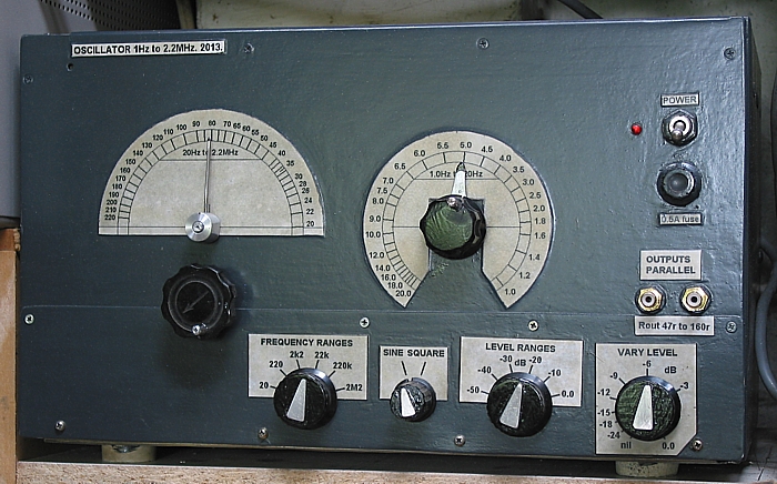
This was nearly completed 2013. Dials and finish were completed
later. The paint finish is a
bit rough but what is inside the box is important.
Notice there are two F dials. Left dial is for AM radio tuning
gangs, and right dial is for an Alps
pot for the lower F.
The dials and labels were made using a PC. A cardboard template
with all F markings is scanned
to make a .gif image in MS paint and in black and white only. The
scan was tidied up in MS Paint.
The tidied dials were printed and altered until I got the sizes
about right after printing.
Because the two frequency dials are circular, they can be slightly
bigger or smaller than originally
intended and the pointers will still point to the same F numbers.
Three printed paper copies were made, then overlaid in exact
position and soaked in furniture
vanish which also acts as a glue to metal case front. Overlaid
copies gives depth to the
printing and looks much better than using just one varnished copy
with allows old numbers and
metal defects to be seen through the opaque varnished paper.
Sheet 1. Wien Bridge oscillator 1Hz to 2MHz.
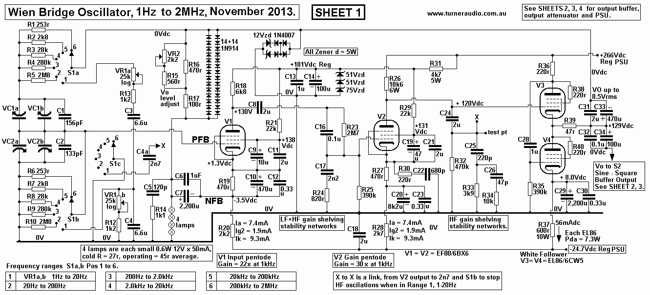
Sheet 1 shows the result after many experiments with different
circuits and tubes to get maximum possible
F = 2.2MHz.
After many trials with triode input stage LTPs with 12AU7 and
6DJ8, the use of 6BX6 / EF80 were found
to be the best for both gain stages, despite the complexity of
cathode biasing and screen bypassing.
Mid frequency open loop gain of V1 + V2 at 1kHz = 22 x 30 =
660.
The gain of the white follower is about 0.75x with all loads used,
so total open loop gain = 495.
The GNFB reduces open loop gain to 3.0 so the amount of NFB = 44dB
approximately.
The open loop gain below 30Hz and above 10kHz is reduced with the
gain shelving networks and
bypassing of V1& V2 470r cathode resistors with appropriate
R&C to give LF stability.
The -24.7Vdc rail enables the use of high value Rk which helps to
keep the anode Vdc very stable,
so direct coupling of V2 anode to White follower V3 grid is
possible to avoid the phase shift.
It is not until anyone tries to build something like this that it
becomes difficult to see how a simulation
program could predict the exact R+C values better than I have with
an old brain. Simulation
programs are so profoundly dumb because they are no better than I
am and they cannot read my
schematics, or draw one like mine.
But I did draw Nyquist graphs of open loop gain and trials of
R&C values and I spent much time
testing before I was satisfied the circuit would not oscillate,
yet give me a passable square wave at
2MHz.
I could get the initial circuit to be stable after initial warm
up, yet half an hour later when using the LF
range I would get bursts of parasitic HF oscillations above 12MHz.
I had to add an extra wafer S1c
to rotary switch, and add C4a 2n7 to reduce HF gain while using LF
range.
I had a number of identical 3-gang AM radio tuning caps and I was
able to mount 4 together using
4mm plastic and plywood. I mounted 4 x 65mm dia 20mm thick plywood
discs glued to cap shafts.
Then I wound polyester non-stretch dial cord around all 4 wheels
and around a 6mm dia shaft
and had spring tension applied, like in old AM radios I applied
some glue to cord at each wheel so
they all turn together
The alternative would be fine chain wheels and tensioned chain but
I found nothing available and able
to be adapted.
The marine ply discs were easy to make using a plumber's hole
cutter blade in a drill press.
Each C gang gives C range approximately 13pF to 400pF. The
effective C range of each C used in
the Wien network for PFB is approximately 180pF to 2,580pF which
includes some added fixed
trimmer C.
This meant having low R value of 253r for the 200kHz to 2MHz
range. The minimum C of about
200pF including stray circuit C and the low 253r gave the F
extension to 2MHz and with stability.
All other attempts with higher R and less C failed to give good
stable results.
The circuit was difficult to stabilize at both LF and HF to get
the full bandwidth 1Hz to 2MHz.
The S1 range switch I have used was an old well made switch from
1950s with 3 poles and 9
positions and I have used 6 positions after adjusting metal work
to only give the 6 positions.
S1a and S1b change the range F, and S1c just switches in the 2n7
to 0V, via link X to X.
So why use so many ganged tuning caps?????
To get up to 2.2MHz the minimum C needs to be above about 180pF or
you get all sorts of HF
or LF instability. If C min = 180pF, then R must be theoretically
= 401r. But you can see I have 253r.
So there must be considerable unknown stray C in the circuit,
maybe 105pF. If C is any less than I
have it, the circuit won't work very well, and for higher F you
would need to think about much lower
R and still keep C highish and use higher gm devices such as RF
signal mosfets etc. I could not find
any schematics online for Wien bridge oscillators able to go to
say 22MHz.
If I wanted a decade of F change per range, and C min was 285pF
including stray C, then max C
would have to be 2,850pF. To get this C variation I needed lots of
variable caps.
Then to get down to 1Hz, the R size = 55.8Meg ohms.
Well, that's quite an impossible R value because the minute grid
current in V1 ruins the function
and you find you just cannot get down to 1Hz with tuning C unless
you had R not more than
about 5Meg. I settled for lowest F with tuning C = 20Hz which
allowed R = 2.8Meg.
I wanted to have fully variable F and a pot for lowest F range
with fixed C was more sensible, and I
could get from 20Hz down to 1Hz. I could have had 24 values of
switched C or R but I would not
have "tunability" in operation. So the LF range from 1Hz to 20Hs
used a dual gang 25k log pot with
a second dial for the LF.
THD is fairly constant at < 0.4% from 100Hz to 5kHz. It would
be possible to have far less THD
but then there are problems of trace bounce and stability, so the
circuit has TWO networks to
manage the problems. There are 12V zener diodes plus 1N4007 to
limit the positive and negative
FB from the output of V3&4. Then I have two strings of 14 x
1N914 in series, facing in both
directions so that once the Vo rises too much, the diodes conduct
and apply MORE NFB to
the 4 series lamps and NFB applied to V1 cathode increases
immediately without waiting for
lamps to warm and increase their resistance, which happens too
slowly, and leads to trace bounce.
Without diode clamping, the circuit tended to oscillate at both LF
and HF when Vdc conditions
changed slightly and briefly at range switching, and at high end
of the 20Hz to 200Hz F range where
grid biasing resistance for V1 is 2M8 in the PFB network. The
phenomena may be called hysteresis,
(( harder to deal with than a hysterical wife )).
This phenomena affects all amplifiers with high open loop gain,
several stages of tubes which draw
grid current at mild overload, lots of R+C couplings, large
amounts of PFB and NFB loop and a
NFB loop. I was amazed that the damn thing worked at all.
It is very easy to make a Wien bridge oscillator with range from
20Hz to 200kHz.
The difficulties occur when you aim for 1Hz to 2MHz.
The diode clamps with 14 x IN914 in series exploit the gradual
conduction beginning at forward
voltage of about 0.4Vdc when current is less than 2mA, and each
diode becomes a low resistance
at 0.72Vdc. With 14, the V range for threshold turn on is from
about 6Vpk to 9.8Vpk.
So the diodes form a non linear voltage controlled resistance
where an increasing applied voltage
causes a logarithmically increasing current, and lowering of
effective resistance. This action rapidly
increases the NFB voltage delivered to V cathode before the lamps
have heated up to increase
their resistance. The lamps have a fairly slow time constant and
diodes have an instant time constant,
so the diodes give an immediate increase of NFB to prevent the
instant rise of PFB from causing
excessive Vo to occur. The circuit settles quickly between range
switching, and once settled,
diodes have only a slight effect while lamps take over the major
part of the NFB regulation of the Vo.
At Vo level of 7.5Vrms, some 3H begins to be produced by the
diodes, but it is better to have that to
enjoy the easy stable operation as a result and without lengthy
settling times and jittery Vo amplitude.
I found that if the Vo level was reduced to say 6.4Vrms by
adjusting VR2, the THD < 0.1%.
You can look at the above Sheet 1 schematic and be repelled by the
terrible complexity and massive
amounts of RC "damping" networks, but if you analyze each stage
and even draw the open loop
response then it all makes sense. If you want such wide bandwidth,
and reasonably low THD, but
with complete LF and HF stability, then complexity is the price.
The open loop phase shift never
exceeds about 100 degrees. With gain reduced by gain shelving
networks the amount of NFB
applied at 2Mhz and at 0.5Hz is very much lower than at 1kHz, so
you get stability. The tubes
are inherently linear at their normal signal voltage levels. The
increase of THD at extreme HF
and LF is difficult to see on the oscilloscope and of no concern.
The F response between 1Hz
and 2MHz is within +/- 0.5dB.
The PFB and NFB networks create the load on the White follower
output buffer stage.
With variable C and fixed R in PFB network the minimum PFB load =
2.11 x 253r = 534r.
Lower F ranges give higher load ohms with less THD and gain
reduction.
NFB network load is 180r in 4 series lamps plus 360r in VR2 and
surrounding R giving total load
NFB load = 540r.
Therefore both PFB and NFB networks give lowest total load = 270r.
The maximum Vo is
determined by the minimum loading and idle current of output
buffer.
Vo max = 7.5Vrms so if load = 270r, then Iac = 28mArms = +/-
40mApk, and idle current in White
buffer = 56mAdc so there is adequate Ia for class A in output
tubes.
EL86 in triode needed to have Iadc at idle of 56 mA and Ea =
125Vdc, with Pda = 7W each,
and less than their 12W rating. The EL86 works better than EL84
because EL86 has 1/2 the Ra
of EL84, hence is less affected by the change of total RL across
each F range, caused by change
in PFB network impedance. The gain of the follower begins to
decline slightly in the top F range
but the NFB boosts the V2 signal to compensate.
V2 has to make a maximum of about 11.5Vrms, well within its SE
capabilities without cut off or
grid current.
Sheets 2, 3, 4 give details for what follows the sine wave
oscillator.
There is a switch for sine wave or square wave, a solid state
discrete component Schmitt trigger
square wave generator with its own amp for +/- 10.1Vpk.
There is an emitter follower buffer to power a low resistance
output attenuator switch for 6 levels
of output in -10dB steps, and a 300r linear output pot to output
terminals.
Sheet 4 gives PSU details including voltage regulators.
Sheet 2. Output buffer and attenuators.
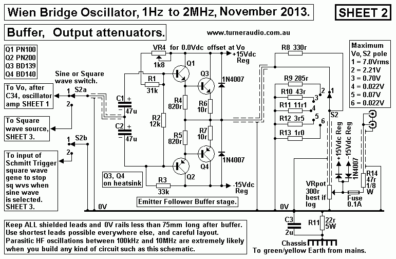
Sheet 2 has npn and pnp bjts in a pair of Darlington connected
complementary emitter followers
to make a buffer stage after sine wave or square wave sources to
drive the low resistance output
attenuators without losing any bandwidth or increasing THD.
The buffer stage is needed to avoid loading the sine wave or
square wave circuits with low R
attenuator networks. and to prevent connections with outside world
devices from having any effect
on the signal production of the oscillator.
The minimum output load for the buffer could be 47 ohms if short
circuit between output and 0V
occurs with switched attenuator in position 1 and pot VR5 is
turned up for maximum Vo.
A square wave of +/-10V peak from buffer will create load current
of +/- 212mA peak, so each
pnp and pnp output bjt must have Idc at idle of about 120mAdc to
allow *class A* power even
when Vo is shorted to 0V.
With +/-10Vpk square wave output the 100mA fuse will blow.
Pd in R14 47r is 2.1Watts and rating is 0.12W so R will blow if
fuse does not.
For all other switch positions buffer load is higher ohms and
signal all class A and THD very low.
To avoid damage by accidental connection of unit output to
damaging voltages, ie anode B+ supply,
or mains active input, the network with R14 47r 0.125W, 100mA fuse
and diodes to +/-15V act
before allowing damaging current into buffer bjts.
Ideally, all signal sources above 100kHz should have low impedance
of 50r to avoid effects of cable
or device input C or L. But because I have gone up to only 2.2MHz
and not to 10MHz, then a
300r output pot is OK.
Little change to the square wave occurs at F above 200kHz,
regardless of level setting.
The bandwidth of the bjt buffer is from DC to 12MHz at least. A
CRO shows no change to the
shape of 2MHz square wave. The rise and fall of square waves at
2MHz looks like the highest
harmonic is about 5MHz. This limited H content is due to simple
Schmitt circuit which was used instead
of other more complex or delicate IC parts which would not produce
the +/- 10Vpk I have here.
There is little use for square waves over 100kHz to what is here
is just fine, and at 5kHz the
square wave is better than nearly everything else I have ever
seen.
Notice the Sheet 2 has a table on how to calculate the resistance
values for this simple switched
attenuator network. This network is very useful for getting an
easily adjustable wide range of output
voltages. A phono preamp can be easily be supplied with a 5mV of
input signal. All good phono amps
for MM or MC carts should survive having 5mV at 20Hz, 50mV at
1kHz, and 0.5V at 20kHz.
With 7Vrms available at maximum level setting, one may test the F
response any OPT and most low
Z inputs of say 600r, knowing the Rout = 50r, and quite low
enough.
Sheet 3. Square waves with Schmitt trigger.
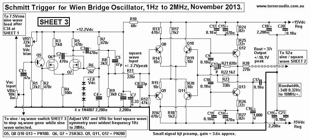
Sheet 3 shows a Schmitt trigger sine-wave-to-square-wave converter
followed by a small signal
discrete bjt op-amp which I developed especially for this project.
Most tubed Schmitt trigger circuits using tubes consist of a
single 12AT7 with each half used in a
similar way to Q6 and Q7 in Fig 4 above. But they struggle to make
a good square wave without
reducing rise times and "rounding of corners" of the wave, ie, HF
content is attenuated.
So while a 10kHz square wave may have F up to 100kHz included, the
100kHz square wave
will have very poor shape so I did not try to use them.
Perhaps a pair of EL86 or EL84 in pentode mode might work better
than a 12AT7.
I leave YOU to try, and I wish you good luck, you will need it.
Here is a result of spectral analysis performed on a 1kHz square
wave...
Graph 1. Square wave harmonics.
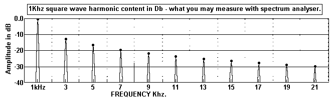
Notice that for a perfect square wave the odd number harmonics
would have to extend to an infinite
frequency well beyond the ability of home brewed test gear to
achieve. But a good looking square
wave will have 21 times the lowest frequency present, what is
called the fundamental frequency,
aka H1, or Fo. The square wave consists of the harmonics above at
the amplitude levels shown.
The zero crossing point of all harmonic waves where Vac is rising
is all the same point at the
point where square wave rises above zero. I show the H for a 1kHz
square wave. Some sig gene
have square wave rise time much faster and the highest H may be
20MHz for all square waves
for the sine wave F range. You may find such generators can only
make 1Vrms of output.
With this in mind, for testing HF stability of amplifiers, use of
a 10kHz square wave
should tell us if there is an unwanted peak in the F response
below 210kHz, something very common
in all too many awfully engineered amps. But seldom will 21 times
H1 exist in any square wave, and
at 2MHz, the attenuation of the 10MHz content and beyond may be
below -35dB and all other higher
H buried in noise.
So to get anywhere near the ideal spectral analysis shown above,
we need fast switching of devices
used to produce the waves. I tried all sorts of Schmitt triggers
with bjts based on what could be found
in books and online. Always the performance failed to satisfy
above about 350kHz, and failed to
function properly by 2MHz.
Googling for an easy way to generate a 10MHz square waves from a
sine wave using a few simple
devices gave no solutions.
But there were very complex schematics with many ICs which like
others online probably failed to
include all associated circuitry to give certain results.
I tried a 4093 C-mos chip, and all ran right out of puff by about
300kHz, and none could have the
necessary trim pots adjusted to give a symmetrical square wave for
all F between 1Hz and 2MHz.
I concluded mosfets would be best because they don't conduct
current at their bases like PN100 or
PN200 bjts especially at HF that they become so mis-biased by
300kHz the circuit becomes
unstable, and there is little wave symmetry and H content is poor,
and Vo level sags.
Sheet 3 shows exactly what I found to be best using a pair of
2SK363 driven at the input by a
PN100 in emitter follower mode.
There is fixed bias of +2.8Vdc at the second mosfet and there are
TWO trip pots, one for input
Vdc bias and the other for the level of input. The circuit works
well right up to 2MHz, without
difficult R+C compensation networks or super critical adjustment
of the trim pots.
The 2MHz wave isn't all that good, and it looks like a 10V peak
sine wave which has been clipped
down to 4V peak with slight corner rounding. But at 100kHz, the
square wave appears to have
H content probably extending to 2MHz, or 20 times the Fo, so good
enough. But my circuit can
make only about +/-2.8V peak. Increasing Vo with a following amp
might reduce H content.
But the amp has BW = 0.3Hz to 12MHz, and good enough. There
is a network R11 + C8
between trigger and amp input to stop parasitic H above 20MHz
between mosfets and input
bjts.
Whatever networks you see used have all been trialled for best
component value.
But this simple amp with 6 bjts works better than nearly all
op-amp chips anyone can buy at
Jaycar, Dick Smith, or The Radio Shack etc.
With the high Vo of +/-10V peak, there is an opportunity to use an
external clipping circuit with
a low value R of say 470r and a pair of 1N914 diodes in parallel
in opposing direction to give
+/- 0.7V peak. Use of 4 diodes could make +/- 1.4V peak. This may
then produce a square
wave of sufficient amplitude to make many power amps clip, and
including much extended F
content.
I have not fully explored possibilities, but fast diodes UF4004,
UF4007, Schottky 1N5819,
are easily available.
Sheet 4. Power Supply.
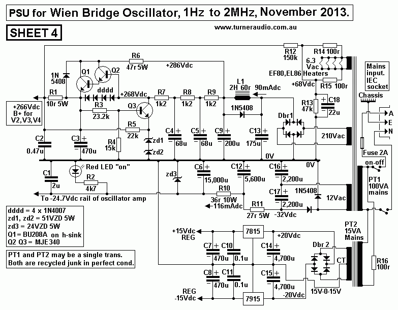
Sheet 4 shows a generic PSU which need not be exactly the same as
any you might build but
you just need make up the voltages and currents as shown and with
the regulation shown with
equal functionality.
One should be careful with discrete bjts used for HV regulation
because all too easily the 3 bjts
use above can all instantly fuse to a sullen short circuit needing
2 hours of work to replace them.
Hence the protection diodes you see, and which you don't always
see on schematics posted
online by idiots who never consider that stuff fails after shit
happens. YOU need to stop shit
happening.
Regulated rails are essential to stop very LF noise appearing in
the output.
Such noise is mostly under 10Hz, but its presence interferes with
tests on amplifiers, so it cannot
be tolerated. The LF rail noise is created by unavoidable changing
mains voltage levels of other
mains users switching on devices continually. Solid state
regulators are so much easier to make
than tube regulators. The +266V regulator works very well. There
MUST be good insulation
between the Q1 BU208 heatsink lest a tiny little arc occur which
will cause instant bjt death.
-------------------------------------------------------------------------------------------------
If anyone want to make a discrete part op-amp for a general
purpose small signals up to 10MHz,
they may consider this......
Fig 2. Small signal amp, bjts.
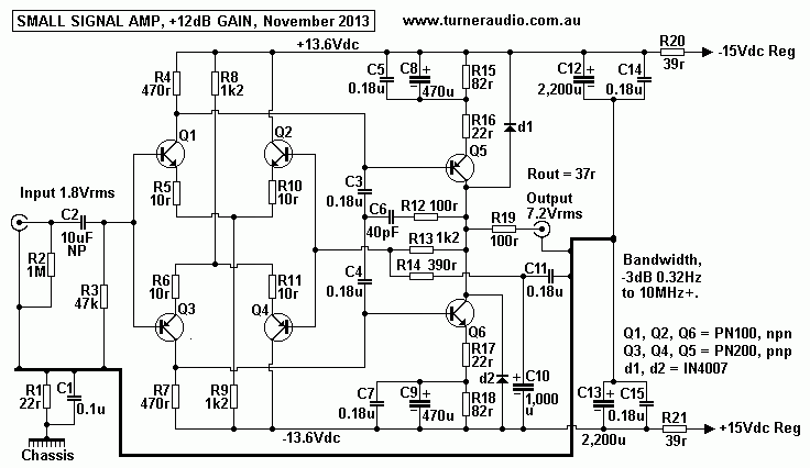
Fig 2 is basically the same amp as in Sheet 3.
But here it is as I developed it and there are precautions about
its use.
It should be used with loads above 600r. It may not like
capacitance loads.
R19 100r increases its Rout, but reduces effects of C loads.
Careful adjustments of C6 & R12
will give best HF extension depending on the load to be driven.
You may have to add a 220r with 33pF LPF at input to reduce
extreme HF oscillation when
used with a preceding amp. But it is food for thought.
Good luck with your soldering.
Back to Education and DIY
Back to Index