Vac meter 1, discrete solid
state. 2013.
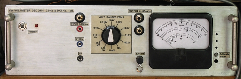
Front panel, 2013.
This page is about the Vac meter I designed and built using an
old analog meter and
rotary wafer switches re-cycled from old test gear made in
1950s. There are 3 "op-amps"
which are built using discrete small size modern TO92 package
bjts and j-fets, plus
modern Si diodes, R and C.
The above front panel and the aluminium box behind was
previously used at ANU for a
meter to monitor vacuum hardness.
Images below include :-
Fig 1. Resistance divider.
SHEET 1. Block diagram for range switch, 3 amps and 1
meter.
Fig 2. Meter Dial.
SHEET 2. Range switch and Amp 1 details.
SHEET 3. Amp 2 details.
SHEET 4. Amp3 and meter details.
SHEET 5. Power supply.
Why build your own signal voltmeter?
It is very good training for the mind. What good are you if you
wish to make new electronic
gear without being able to build a good signal voltmeter which
works as well just as well
or better than products for sale costing hundreds of dollars?
What makes a good signal voltmeter?
Most voltmeters meters on the market are "digital" multi-meters,
DMM, and usually hand
held units powered by a small 9V battery.
They have numerous ranges and functions and readouts. All these
are very easy to use,
especially types with auto range selection,
like a Fluke 117, a good brand.
Advantages :-
1. Light weight and size.
2. Large number of functions, Vdc, Vac, Amps, continuity, peak
and hold,
diode and bjt properties, frequency, inductance, capacitance.
3. Resolution to 4 significant figures.
4. Able to be used in "floating" mode to measure across 2 live
circuit points.
Disadvantages :-
1. Fragile when used with tube circuits; likely to fail easily
from high voltages
applied at input, often higher than DMM the unit's maximum
ratings.
2. Over time, they slowly lose functions, and become impossible
to fix.
3. Cannot read Vac where a lot of Vdc exists.
4. Cannot read Vdc where a lot of Vac exists.
5. Take far too long to settle down to give a measurement.
6. No back lighting to LCD display.
7, Display has many range selections but text size is far too
small and decimal
points don't show prominently.
8. Bar meter is inadequate.
9. Cannot read Vac frequencies accurately below 7Hz or above
1kHz.
10. Have rather high input capacitance for Vac.
11. The 9Vdc batteries go flat too soon, maybe in 1 month with
constant use.
The first Fluke DMM I bought in 1993 gave most functions
for 20 years.
But the millivolt Vac range died, then resistance measurement
died, then Vac range
was erroneous, so it became useless junk for the re-cycle bin.
But it out-lasted about
4 other DMM I bought from Jaycar, of Digitech brand which was
the worst.
The 1993 Fluke had most of the advantages and few disadvantages.
My replacement Fluke 117 has a few more useful functions and is
acceptable.
But the next Fluke 117 I bought was not as good as the
1993 model it replaced.
When using Vac auto range the meter could not read 0.0Vac. The
lowest Vac was always
0.022Vac minimum displayed. When using the mV range for Vac, any
presence of Vdc
obliterates the measurement of Vac, so you must use a 0.01uF cap
in series with red
lead to measure low Vac where any Vdc was also present. But then
the readout of low
level Vac becomes slow, no better than the awful Digitechs etc.
And you cannot read
below 3mVac accurately. One must get used to a new item where
obvious shortcomings
are never described in manuals or data for the item. Fluke
manufacturing in USA was
transferred to China, and the quality seemed to nosedive.
After becoming fed up with the first Fluke 117 I bought,
I examined another in a store
which sold to electricians, and this one was OK, red right down
to 0.0Vac with the Vac
and mVac ranges, so I bought a second Fluke 117. I have retired
from trades these last
few years but the later Fluke remained OK. So there must have
been something wrong
with calibration of the first one, but I could not see anything
adjustable within the case.
To avoid 9V battery replacement I used 6
x 1.5 D-cell batteries soldered together in
series to make a single large long life 9Vdc battery. These are
then wrapped with
insulation tape between two sheets of thin plywood to make them
well insulated from
anything on the bench or in equipment. You could also explore
use of rechargeable
batteries. Such batteries lasted years.
Be VERY CAREFUL measuring any high
voltages!!!!!
It is always dangerous to work on tube circuits even when there
is only +/- 200Vdc pk.
All Vac above 100Vrms can be dangerous.
When working with transmitting tubes such as 845, 813, the anode
supply Vdc may
exceed +1,000V. These voltages are HIGH and LETHAL.
The high Vac and Vdc in vacuum tube gear can easily destroy
solid state test equipment.
All octal output tubes such as 6L6GC, EL34 or KT88 can have
combined anode peak
Vac and Vdc exceeding the 600V typical max input voltage allowed
for a DMM.
To minimize meter damage, always measure Vac at anodes
between anode and from
B+ input to OPT to avoid including high Vdc with the Vac being
measured.
Always monitor Vac at OPT sec with CRO.
So you always anticipate what you may expect at anodes or
OPT primary windings.
A single 845 making 24W into load of 12k0 generates 536Vrms, or
+/- 758Vpk,
and Vdc at anode with cathode biasing could be 1,250Vdc above
0V. Any DMM
could easily be fried to a crisp.
A PP amp with KT88 tetrodes may normally have B+ = 480Vdc, with
270Vrms at
each anode for 36W to RLa-a 8k0. But if there is no sec load
connected, and high
input signal, Va-a can become 4 times the 270Vrms due to energy
stored in leakage
inductance so that each anode can have Va pk = 2,000V above 0V.
You have been warned!
YOU must THINK before making any
measurement !!!!
You must know exactly what you are probing, and estimate what
could be the
highest voltage likely to be found. To work on tube gear you
really need to have
a couple of fixed resistance dividers on circuit boards in
plywood cases and fixed
on panels near the work area to allow meter leads to be
connected to low voltage
output from divider and probe leads then taken from high Volt
input for divider.
You may think a 10:1 reduction CRO probe is both sensible and
handy, but they
are no good for HV. Much better insulation is possible with a
fixed resistance
divider.
All test gear should have input protection preventing damage
when Vin exceeds
1,000V. Not all DMM have such a high max Vin rating. I once
accidentally applied
a pulse voltage over 2,000Vpk to a solid state LabTech CRO. The
repairs cost far
more than what I'd paid for it, and the complexity meant I could
only keep
replacing chips and bjts etc until it worked, and it never
regained all its functions.
It then developed more faults so it went out with the rubbish. I
repeatedly burned
the output bjts in a solid state function gene. This was due to
accidentally allowing
its output to be momentarily connected to something in a tube
amp at more than
100Vdc. I repaired it several times but I finally murdered it in
cloud of smoke and
bad smell after allowing its output to contact 240Vac mains for
2 seconds.
I had fitted protection but even that failed.
So I forced myself to learn good
workshop habits.
Do not clip meter leads between tube anodes and 0V. Try to avoid
using any leads
with alligator clips, especially non-insulated types because
sooner or later,
you will touch the wire on meter to a HV, and POOF. Do not allow
any ends of
leads to gear to lay unplugged on bench. If any lead from a
signal generator or
voltmeter is not being used, unplug the whole lead.
A stand alone cathode follower in a box can be a good buffer
between all signal
genies and amp inputs or outputs. This can be arranged to have
many megohms
of input Z and high bandwidth. It is also possible to make a
fully floating buffer unit
with mains supply also floating with well separated primary and
secondary mains
windings. The cathode follower output may drive a 10k:1k0
transformer with
insulation rating 4,000V, so that Vac readings across two active
circuit points at
different Vac and Vdc may be made, while the transformer sec
always remains at 0Vdc.
But iron cored transformers have limited Vac range and
bandwidth, and add some
distortion to Vac.
Use an RCA input socket when "bread-boarding" a new circuit so
stray contact to B+
or high Vac output is less likely. I often make sockets for 2mm
or 4mm probe leads
using say 6 turns of 1.2mm dia copper wire and soldered to the
0V rail on board.
So risk of the OOPS moment is dramatically reduced.
Most of the electrical shocks I had were from unguarded
mains input wiring.
Although the item is turned off, there are often live Active
terminals before the mains
switch and which have not been covered with protective
shrouding. Always place
covers preventing contact to live mains inputs.
For HV measurements without shock or wrecking meter, here are
details of a
resistance divider so that a possible 4,000V can be reduced to a
maximum of 400V.
Fig 1. Resistance divider.
The above resistance divider can be made using circuit board
inside a sheet
metal which MUST be connected to EARTH. A strongly made plastic
box could
also be used which does not need to be earthed.
The input leads to divider must have good insulation rated for
5,000V which may
possibly be purchased as spare input leads for the best of Vac
meters.
I show TWO Vac reduction ratios, 1 : 10 and 1 : 100. Both Vac
and Vdc can be
inputted, or Vac only if C1 is included. C1 = 15nF, and LF pole
with 10M0 Rin is
at 1.0Hz.
The exact reduction ratios will only exist where VR1 and VR2 are
adjusted to suit the
Rin of a Vac meter connected at output.
Consider use of Vac meter with Rin = 3M0 connected from output
to Com.
For 1 : 10 measurement, switch S1a+b for 1:10, the total of (
R10 + VR1 ) parallel
with 3M0 meter must be 1M0. Thus VR1 will be set for 500k. This
setting maybe
be kept for all meters with Rin = 3M0. The lowest meter Rin =
2M0.
For 1 : 100, set S1a+b for 1 : 100. The total of ( R12 + VR2 )
parallel with 3M0
meter must be 100k. Thus VR2 is set for 3k4.
The lowest meter Rin can be 500k for 1 : 100 ratio.
The input resistance to the R divider = 10M0. There is always
capacitance for
any probes for Vac meter or CRO, and if C = 10pF, input
impedance input of
divider begins to reduce with -3dB pole at 1.59kHz if the
circuit measured has
infinite impedance. Where the circuit has no C and R = 100k,
then 10pF gives
pole at 159kHz.
Most high Vac measurements in audio amps will involve circuit Z
> 10kHz, and
F > 200kHz, so the 10pF divider will not reduce HF very much.
For above 100kHz, and where it is possible without affecting the
circuit measured,
it is better to use an RF probe with diode and low C to convert
the high Vac to
Vdc without loading the circuit, and then you measure the peak
Vdc which is
converted to Vac by calculation.
The R divider is somewhat painful to use, but it avoids use of a
more complex and
expensive arrangement.
Measurement of Vdc should be very accurate using the divider
when VR1 and
VR2 are adjusted for the 1 : 10 or 1 : 100 ratios.
Most Vac meters have Rin at dc > 5M0.
For Vac measurement where a number of meters or CROs are to be
driven and
high bandwidth is wanted, or a Vac meter plus CRO has Cin >
100pF, an EL84
in triode cathode follower mode may be used with a stand alone
PSU of
say + 300Vdc for anode and -300Vdc for cathode resistor.
The there may be a 0.1uF coupling from R divider to EL84 grid
with grid bias
Rg 330k and bootstrapped 330k from bottom of Rk 1k4 from cathode
in series with
28k 10W to -300Vdc. Idle Idc = 10mA approx.
Heater for EL84 will be from floating 6.3V x 0.8Adc supply,
arranged from small
PT from mains with low C between mains and Vac winding.
The gain of EL84 will be 18, reduced to 0.9 in follower mode.
The effective Rin
with bootstrapped 330k is over 5M0. Cin should be less than
20pF. Noise should
be < 0.5mV, and not disturb measurements of more than 1Vrms.
Output from cathode follower is from cathode which will have Vdc
at about +14Vdc,
where Eg1 bias = 0V. There must be a 0.47uF cap from cathode
with 330k to 0V to
keep output side of 0.47uF at 0Vdc. LF pole of CF will be about
1Hz.
The VR1 and VR2 can be adjusted to be more than 1M0 and 100k
respectively so
that to obtain say 50Vrms at CF output, Vg input = 55.6Vrms,
where Vac to be
measured = 500Vrms. Thus VR1 or VR2 can compensate the CF gain
of less than 1.0.
With all reductions of Vdc or Vac input with an R divider, the
accuracy is always
challenged, despite whatever care is taken. But most technicians
do well to
measure say 97Vrms to 103Vrms where in fact there is 100Vrms.
Most measurements
of Vac are made to compare Vac at different F, and the R divider
allows the
F response to be examined at an anode powering an OPT.
Remember that where Vin = 3,000Vrms, Vac across each R1 to R9 =
300Vrms.
Current in each 1M0 = 0.3mA, and very low, so 1W metal film
ought to be OK.
But R1-R9 must be rated for 450Vdc and I suggest these be tested
with 500Vdc
for several hours before using them. Their heat will be 0.25W,
and should feel
warm. ( DON'T touch them with 500Vdc flowing ).
There are CRO probes available with 10:1 or 1:1 selectable V
ratios.
These are often better made than anything you might make and
have have 10M
input Zin so that there is 9M + 1M and the 9M is at the tip of
probe and it has low
Cin < 15pF. There is often a tiny trimmer C across 9M0 which
is adjusted for best
square wave of say 20kHz when using the probe with cable C =
67pF and CRO
Cin = 33pF, for 100pF total.
The problem with such CRO probes is their fairly low Maximum Vac
rating.
I would suggest testing circuits with 3,000V present could lead
to destroying a
meter or a CRO.
But for say 200Vrms, 10 : 1 CRO probes are very good for
observing wide
bandwidth Vac where the CRO or meter has "matching" C in of
about 33pF.
It is difficult to measure low level RF Vac at high impedance
tube circuits, eg,
at output of IFT1 at input of 455kHz IF amp grid of 6BA6 in AM
radio.
Many 455kHz IFT LC will fixed C of say 200pF, and adding say
20pF will
change Fo and lower Vo, and cause THD in detected audio F.
A cathode follower using say 1/2 6DJ8 may work well, and Vac
will be less
than 10Vrms, and Cin < 5pF if the tube is mounted at the end
of the probe to
allow short grid input wire of 30mm. It is easier to make a
small size 10 :1 R
divider with 900k + 100k and keep C r in across 100k less than
67pF, so that
C across 900k is less than 7pF. The 1M0 is high enough to
prevent reduction
of Q of LC, thus reducing Vac measured.
This website is not meant to fully explain RF phenomena or
techniques, and
best practices are part of a well trained and disciplined mind.
Lower R values for R divider may be used where circuit impedance
at DUT is
less than 10k, and if total R = 500k the Vac reduction with 500k
load is from say
100Vac to to say 98Vac, or -2%.
If measuring Va at EL34 anodes, R-divider could be 500k + 56k,
and this gives
100V : 10.7V ratio. If Vdc or Vac = 500V, current = 1mA, and OK.
If anode circuit
impedance = 5k0, then error is very low.
I often use an oscilloscope, ( aka cathode ray oscilloscope, or
CRO, ) because
it has a vacuum tube within to display wave forms without
telling lies, so you
SEE what is happening. I have a 1983 dual trace Hitachi and a
dual trace
Tektronics 465, both nice to use with reliable solid state to
drive cathode ray tube.
Bandwidth is DC to about 15MHz. But they are allergic to
excessive Vac input.
A CRO is not capable of accurate measurement, but for very many
audio
measurements the F response around various parts of a given
circuit can be
quickly recorded at +/-3dB, 6dB, 12dB. It may be compared to
response at input
with dual trace function. THD > 3% and phase shift > 5
degrees are easily seen,
all much faster than listing many Vac levels at a meter.
An old fashioned CRO with 15MHz bandwidth is better than a hand
held digital
CRO or PC with sound card etc. Cheap second hand CROs should be
plentiful.
I did not ever buy a tubed CRO because all that I found had worn
out tubes and
worn out cathode ray display tubes.
I built my first bench Vac meter in 1994 with mains PSU in small
box with SS bjt
discrete circuit with 6 ranges from 0 -10mV to 0 - 1,000V.
Bandwidth was not too
bad at -1dB at 2Hz to 200kHz, with some extending to 1MHz, but
HF response
above 200kHz was not flat. There was one amp using bjts with
gain = 100.
Input Rin was 500k to switched input R divider, and each Vac
range made to suit
the single 0.0 to 10.0 scale, so any reading below 1.0 was a
guess.
I added j-fet input after the switched R divider and some
protection. But I found to
measure Vac between 0.0 and 1.0 in the scale needed more Vac
ranges for 0.0 to
3.2 scale, and then low Vac for a 1-10 scale is seen much
better. There were passive
germanium diodes to give peak Vac, and scale was calibrated
using low THD sine
waves so that what was read was Vrms for sine waves. But a
square wave or triangle
wave gave the same peak Vac so a calculation was always needed
for Vrms for non
sine waves.
Between 2013 and 2014, I discarded the old Vac meter and totally
rebuilt the meter
according to schematics below. I retained the same old analog
meter with its 100mm
wide dial face with enough room for three scales, 0 - 10, 0 -
3.16 and a Db scale,
immensely valuable for quick response checks to about 3
significant figures.
FUTURE IMPROVEMENTS if I ever get time :-
Floating balanced input. This could be done using a 1:1 or 10:1
AF transformer at
input with a nominal input Z = 20k to secondary 20k or 6.3k.
Core saturation should
not occur with 20Vac input and below 10Hz. Such an AF
transformer needs good
shielding and primary Lp = 300H minimum, and would need mu-metal
core to reduce
distortions and it is not so easy to R&D such a thing.
Alternatively, one must build a wide band Vac meter with
re-chargeable batteries
for + / - Vdc rails. This could be difficult, but there are no
bandwidth limitations of
a transformer. The mains powered +/-Vdc rails and 0V rail may be
switched to meter
rails for single ended input with 0V tied to EARTH, so that
during most operation,
batteries are charged.
I also have a hand held DMM powered by +9Vdc from a mains plug
pack PSU
from mains. The PT is low VA, and has its secondary well
insulated from PT
primary so making floating Vac or Vdc measurements between any
two circuit
points is easy without use of batteries. It does work, but where
circuit impedance
is high, there is 50Hz interference because of the C between PT
sec and mains
winding.
To avoid this, a special single C-core mains transformer is
wound with mains
on one side of the core, and secondary on other, to reduce stray
C between
P and S. A shield over mains coil can also help reduce 50Hz
interference.
Once done, this is a very simple arrangement.
-------------------------------------------------------------------------------------------------
Vac meter 1 details.
SHEET 1. Block diagram.
SHEET 1 shows a 12 position wafer switch is used with 3
amplifiers to power
an analog meter.
The content of SHEETS 2+3+4+5 are within dashed lines......
Case = 425mm wide x 135mm high x 250mm deep, 1.6mm Aluminium,
except front
plate = 3mm thick. Heatsink for PSU regulators is aluminium
plate between PSU
and amps. The whole of SHEET 2 and SHEET 3 and the rear of the
meter itself is
encased in internal steel box to give some magnetic shielding
and ensure low noise
with amps having input impedance above 20Meg even when using the
0.0 - 1.0mVac
range.
My meter dial can be copied into your PC image program and
changed in size to
perhaps suit your meter. Most analog meters have swing of more
than 90 degrees
as mine shows.
Fig 2. Meter Dial.
I made a template using white cardboard and pencil to plot the 3
scales using my
Fluke to verify voltage measurements. The scale is substantially
linear, because
the Vdc used to drive the meter is derived from the GNFB network
of a meter amp.
For changing Vac ranges, I used an old double rotary wafer
switch with 12 terminals
for 12 positions. These old switches commonly used terminal No12
which was also
a pole which points to itself at position 12. So I could get
only 11 Vac ranges from
0 - 1mV to 0 - 100V.
The 0 - 316V is possible by having a non switched 4mm banana
socket for only
316V when the 100V Vac range is selected.
The meter is calibrated so that a pure 400Hz sine wave at
10.0Vrms gives the same
reading as my Fluke digital meter. Other readings above and
below 10V are consistent
with a good DMM.
I did consider rigging up a 2.50Vdc reference diode so peak Vac
of a Vac source
could be adjusted for 2.5peak, ie, 1.767Vrms, and the meter amp
gain adjusted so
needle sits on 1.767 Vrms on 0 - 10V scale. But the Fluke seems
to be accurate
enough, and its better to have two good meters which give the
same Vac reading,
even if they are slightly in error by up to +/- 2%.
SHEET 2. Switch details and Amp-1.
For the low Vac ranges 1mV to 100mV.
The 5 low level Vac inputs are fed from input RCA or banana
socket through 10k
bypassed with 15nF. This R&C prevents excessive input Idc
flow in limiting diodes
at Amp 1 and Amp inputs. The input blocking caps charge up
slowly.
The 10k is thus a protection measure. Once all coupling caps
charge up within
the unit there is very little delay waiting for Vac reading to
settle.
The input is fed to terminals 1a to 5a and then to input of Amp1
which has a
j-fet 2SK369 with bootstrapped bias R21, so input Z = 20Meg with
some shunt
capacitance of mainly Cg-d of 15pF with maybe 5pF of other stray
C.
For Vac ranges 1- 5, Zin = 20Meg bypassed with 20pF.
The source follower connection reduces the Cg-s from 75pF to
negligible amount.
So, any input signal will see 20Meg at 50Hz but the 20pF reduces
Zin at 6dB / octave
above 400Hz. The Zin is about 1Meg by 8kHz. For most amplifier
measurements
the Vac being measured has source resistance below 50k, thus
allowing HF -3dB
pole at 159kHz, assuming the source is not already shunted by
any additional
capacitance.
Amp 1 increases signal 10.0 times, and feeds its low Z output to
R divider R3 to R7.
Amp 2 selects signals via pole to points 1b to 5b. At each Vac
range the Amp 2 input
is a maximum of 10.0mV max for the 5 ranges.
Amp 2 increases signal 10 times to provide a maximum of 100mV to
power Amp 3.
Amp 2 input also has a bootstrapped source follower with Zin
about 15Meg bypassed
with 20pF.
Amp 3 converts the Vac to Vdc linearly to work the meter for
full swing.
Output from Amp 2 of up to 100mV can be viewed on oscilloscope.
For all input signals above 100mV, Amp1 is not used and input is
directed to each
separate R divider for each of 6 Vac ranges.
Each of these R dividers has Rin = 3.06Meg, with much less R as
the series R.
For all Vac ranges from 0.316Vac to 100Vac the Zin = 3.1Meg
bypassed with about 4pF.
There are many capacitors which need critical adjustment. C3 and
C23 are small
ceramic trim-caps set to minimize any oscillations above 1MHz.
These are very likely
if there is poor layout, inputs close to outputs, or if electro
rail caps are not bypassed
with plastic caps and if leads are not all kept extremely short.
I've used a number of
220r "gate stoppers" to prevent spurious HF above 1MHz.
Caps C9,12,14,16,18,20 are made with a 12mm length of 1mm copper
wire soldered
to switch lug with small piece of 0.5mm insulated telephone hook
up wire soldered to
other switch lug, and then wound around 1mm wire until response
from a signal gene
showed best HF extension without peaks or troughs, and a good
looking 40kHz square
wave.
Caps C11,13,17,19 were chosen after each of the others was set
for about 3 turns of
wire wrap, ie, about 4pF. Once the response looked nearly flat
and square waves had
little peaks or rounded corners the wire wrap caps were adjusted
for best flat response
and best square wave.
I was able to get all ranges from 1mV to 100V to give bandwidth
giving -1dB at 1.4Hz
to -1dB at over 250kHz with less than +/- 0.2dB change along
each band. The source
signal comes from the low impedance output from a completely
re-built 1980 BWD
function generator with F output from 0.1Hz to 2MHz.
SHEET 3. Amp-2 gain = x10.
Amp-2 is explained well within text on the schematic. You may
find this amp
could make a splendid line level audio preamp.
SHEET 4. Meter Amp-3.
The meter amp uses 4 germanium diodes in a bridge rectifier to
create a small
Idc flow to power the meter. This diode bridge and meter is
within the NFB
network with R11, R14, VR1. The total value of these three
resistors = 73r.
If you make this circuit, the R values will need to be different
to suit the meter
used.
The GNFB action makes the conversion of Vac to Vdc linear. The
FB virtually
eliminates the the non linear forward voltage turn on transfer
function of diodes.
Calibration of the meter is by applying 100mV to Amp3 input, and
turning shaft
of VR1, 300r, so that the meter has a full swing.
VR1 is a 25mm pot mounted on the board and its 6mm dia metal
shaft to a plastic
shaft with screw slot and protruding through front panel where
it is not likely to
be disturbed. Once set, the calibration has shown no sign to
drift. The NFB
eliminates all non linearity including temperature drift.
Replacement of the
meter would require the NFB resistance network values to be
revised.
C3+R5a, C8, C9 are needed to prevent HF oscillation above 5MHz.
Probably, the smart arses among you will laugh at my primitive
circuit.
And you may find ordinary op-amps would be easier, until you
realize most
do not have the ability for such wide bandwidth. It would be
nice to have
HF -1dB pole at 5MHz or higher.
But once you get to RF, measurements are difficult unless the
circuit
impedances are much lower. This Vac meter is meant for the audio
tech
needing to know about signals between DC and say 500kHz.
SHEET 5. Power Supply.
There is nothing unusual about this generic PSU. The R3,4,5,6
47r plus
bypass caps seem to fully suppress any stray coupling at any F
between
the 3 amplifiers which would cause serious stability problems.
Back to Education and DIY
directory
Back to Index page