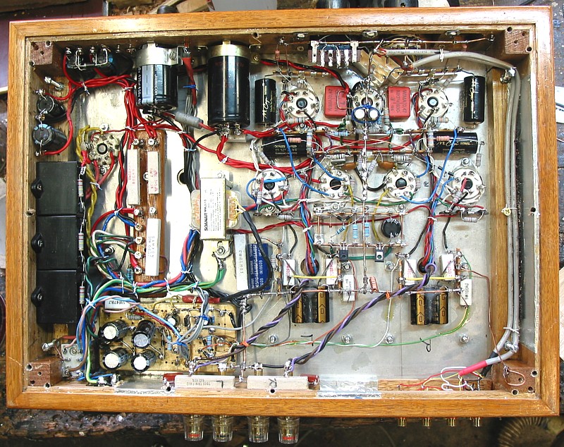
TRANQUILITY PP 30W UL AMP, REFORMED 2010.
The above schematics show my work on an integrated 30+30W UL
amp made in Victoria in in about 2003.
I won't say who made it, but the model name was "Tranquility",
but the buyer of this one didn't experience much tranquility when
he tried
to use it, so it came to my work bench for re-engineering.
The original had about 1/3 of the parts count which I have used,
and
produced noise, high THD, high Rout.
There were three 6SL7 tubes for input&drivers for both
channels,
and 2 x KT66 for each PP UL output stage.
But only 2 triodes were used out of a possible 3, with one
providing gain to
make needed Vg for one KT66, and other to invert the phase,
and no GNFB used. So without GNFB and one noisy 1/2 6SL7, the amp
had high THD, very poor damping factor, and lots of noise.
However, the 4 main iron-wound items, PT, filter choke, and both
OPTs
were quite well made, and I saw potential for me to convert this
pile of junk
to another example of best practice if I gutted the entire
under-chassis wiring and
installed my new circuits.
Two years have gone by with no complaints from the owner.
There are 3 x 6SN7 tubes for each channel's SET input and LTP
driver,
plus bjt CCS common cathode current for LTP. Critical damping
networks
prevent any oscillations, and GNFB made a huge improvement to
sound.
I don't have a picture of the top of the amp.
The transformers seemed to be copies of old A&R units from
1960,
with E+I and bell ends, with "crinkle tone" paint, very retro.
OPTs had sufficient bandwidth to allow unconditional stability
with GNFB as I have
it in the schematic. I have no clue what lamination quality was in
all wound items.
But PT ran quite hot, so its E&I could not have been GOSS.
Appearance was fine.
But if the amp is dropped off a bench the 19mm timber used for
chassis sides turns
to splinters.
The owner took my advice to make a new bottom cover using 2mm
aluminium.
He had access to a drill press for metalwork classes at a school,
and he spent
an hour drilling the bottom cover with as many 8mm dia holes at
20mm c/c as possible
according to a plan I sent him. This allowed some ventilation of
parts under the chassis.
I fitted the new cover to timber recess with many 50mm long wood
screws for better
resistance to dropping. Finally, I fitted 15mm feet under bottom
cover to allow air flow
up through holes in bottom plate. Such amps MUST NOT ever be
placed on plush
carpets, and MUST only be placed on benches or a table.
The trend of using timber + flat metal top&bottom plates is
something many DIYers
do to avoid bending metal on the kitchen table to make a full
chassis.
This amp had 2mm stainless steel top, good looking, but very
difficult to drill.
The existing amp has its original screened IEC mains socket &
fuse holder,
output terminals and input terminals on rear panel. Mounting all
these nicely
in 19mm timber is much more difficult than through metal sheet.
Mains switch and volume pot, source switch are mounted through
19mm
front panel. These required recessing timber behind panel down to
very thin
thickness to allow mounting. This meant I had to put in metal
plates to hold
controls better because timber can only be 3mm thick, so fragile,
and the pot and
switch could easily be pushed inwards breaking the timber.
DIYers and lazy stupid manufacturers do not consider the
consequences of
their shortcomings.
I conclude timber surrounds on power amps is bad practice, wasting
more
time than anyone wants, and it needs to have paint finishes
applied, weakens
the amp structure, and does not give natural shielding, and does
not improve
the sound.
So, if YOU build an amp, please use 30mm marine grade plywood at
least.
AND put in metal 20mm x 20mm angles inside corner joins with 8 x
25mm x
4mm dia wood screws to hold corners together.
Top plate and bottom cover plate should have 4mm c/s wood screws
at 100mm c/c
and there should be a perforated steel sheet cover over tubes.
If you don't like having a power amp chassis made by a metalworker
then for a chassis
which is all metal, easiest is to use 2mm flat plate aluminium for
the top and bottom,
and then use use 75mm x 25mm x 3mm thick aluminium channels for
the 4 sides
of chassis.
These can be cut with a hacksaw with channel held on bench with
clamps with cloth
to prevent marking aluminium surfaces.
The cuts are 45 degrees and filed clean to make a nicely mitred
join at corners.
The outside sharp corners may be filed to make a round to prevent
you cutting
fingers each time you move the amp. The chassis parts can be held
together
with M4 countersunk screws with nuts inside chassis space.
Such work is usually beyond many DIYers who try to build an amp
after a
lifetime of never ever building anything or getting their hands
dirty.
The amp had no top cover. This ensures that when owners move their
amps,
and put it on back seat of a car, and when they stop suddenly, the
amp may roll
forward onto the floor, breaking a couple of tubes.
This amp had Chinese KT66, "similar but different" to original
KT66 which
probably were meant to be used. The owner said the sound was just
what
he wanted and expected, naturally smooth and warm, yet losing no
definition
and detail.
Back in about 1957, Wireless World magazine published an article
on how
to make a 400W amp with 10 x KT88. The finished amp had all its
parts screwed
down onto a 25mm thick plywood sheet about 700mm long x 250mm
wide.
There was a simple perforated steel cover which was screwed to
edges
of plywood. A top cover could be 1.6mm perforated steel sheet with
say
5mm holes and 50% open, bent and joined to form a box.
You end up with something that looks like it belongs in a back
room
of 1950s stadium. Very retro.
Back to Re-engineered
amplifiers
Back to Index