Mr Zel's Cobra integrated amp, 2011-12.
In this page, I review the work of a local craftsman and provide
more thoughts for everyone
about circuit techniques. I supplied Mr Z's OPTs and filter
chokes, and gave a schematic to
best suit the OPTs.
Picture 1. Amp on bench, not quite finished.
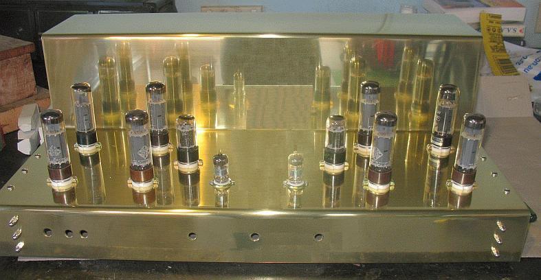
Mr Z's metalwork uses 3mm polished
brass sheet for the stereo amp chassis.
The work is not quite fully completed in this pic, but you get the
idea of what is possible.
The three central holes in front panel are for L + R gain setting
pots and a rotating source switch
between them. Tube line up for each channel is 6DJ8, 6BL7, 4 x
EL34. The EL34 could be
replaced with many other types of tubes such as 6L6GC, 5881, KT66,
KT88, KT90, KT120,
6550. But if these alternatives are used, the bias setting
networks must be altered to give the
correct range of grid voltages.
Fig 1 below shows the schematic for one channel but without the
source switch and gain pots Mr Z
has used at the input. With 4 x EL34, each channel is capable of
nominal power of 62W with OPT
being 5k0 : 5r4, and with load of 5r4. Any speaker value above 2r5
may be used to give acceptable
sound quality for nearly everyone in a normal domestic room. The
5r4 nominal outlet Z ohms means
that
speakers above 5r4 will give more pure class A and best hi-fi but
marginally reduced maximum
Po and speakers below 5r4 give less class A but higher maximum Po
and yet sound should remain
excellent. With KT88 / 6550 / KT90 / KT120, higher maximum class
AB Po is easily available with
lower loads, while maintaining high class A working because these
larger tubes may be biased at higher
Iadc. My 8585 amp shows what is possible. Fig 1. Input, driver and
output stage.
Fig 1. Schematic of 80W amp.
Output stage capabilities.
The OPT available for this amp suited 4 x EL34 or many other octal
output tubes. With any output load
above 5r4 such as any nominal 8r0 speakers, the loading of EL34 is
in a natural linear region where the
OPT CFB is enough to lower the Rout sufficiently, and keep THD /
IMD low enough to dispense with the
10dB Global NFB network C2 & R5.
Output loads lower than 5r4 give less class A1, more AB, higher
maximum Po, higher THD/IMD and lower DF.
Output loads higher than 5r4 give more class A1, less AB, lower
maximum Po, lower THD/IMD and higher DF.
The speaker load affects the voltage gain of output tubes. The
lower the load ohms, the lower the output
tube gain where gain is open loop, ie Va-k / Vg-k.
The CFB within output stage above shows that Va-k = 280Vrms, and
Vg-k = 20Vrms, so open loop gain A = 14,
but with the series voltage CFB the closed loop gain A' becomes =
A / ( 1 + [ ß x A ] ) = 3.11.
Or as observed, A' = Va-k / Vg-0V = 280V / 90V = 3.11.
The amount of applied FB = 20 x log A / A' = about 10dB.
The output stage shown will produce higher output power with half
the RLa-a shown but the lower load causes
higher THD and the lower open loop gain A is much reduced so
applied becomes lower so THD is about
doubled when the RLa-a is halved. With 25% CFB as shown, and at
62W just under clipping, and output load
= 5r4, THD will be < 2% without GNFB. At average levels of 1W
the THD will be < 0.2%. If GNFB is used,
the 2% at clipping is reduced to < 0.5%, and at 1W the 0.2% is
reduced to 0.05%.
For nearly all pentodes or beam tetrodes, the ideal load which
produces the lowest possible THD & IMD at
clipping is just above the load giving the maximum possible pure
class A Po, in this case, when speakers
= about 10r0.
Use of KT66, 6L6GC, 5881, 807, 6550, KT88, KT90, KT120.
The use of the larger octal tubes with higher Pda ratings and
different biasing voltages requires a mention because
some ppl might copy the schematic of Fig 2, then plug in KT88
without any thought about biasing consequences.
KT66, 6L6GC, 5881, 807 may usually be used instead of EL34 / 6CA7
and the only change needed is to grid
bias Eg1, adjusted to give same Iadc at idle.
Calculating the wanted grid bias is a Royal PITA for most ppl not
yet used to the variety of what tube might be
used or their different idle Pda and Pdg2 and hence different Iadc
and Ig2 at idle.
Calculating Grid Bias voltage, Eg1.
The grid Eg1 bias voltage can be calculated within +/- 10%
:-
Eg1 = [ ( Iadc x Triode Ra ) - Ea ] / Triode µ.
1. This is true for all negatively biased triodes and can be
applied to power pentodes and beam tetrodes,
and where :-
2. Triode Ra is is average value for Ra curve for Eg1 = 0.0V
between 0.0mA and Iadc at idle.
3. Triode u is read along horizontal line for idle value of Iadc.
4. Ea is taken as the screen Eg2 where Ea is higher than Eg2 in
cases where true pentode or beam is used
including CFB applications.
5. For triode strapped pentodes and tetrodes and for UL, Ea = Eg2.
6. Ea or Eg2 is always the Vdc between anode and cathode or
between screen and cathode.
Example, EL34 in above schematic, Ia = 38.75mAdc. Ra for Eg1 = 0V
at this Iadc = 1k3. Triode µ = 9.
Ea = 450V, but we will use Eg2 = 300V.
Eg1 = [ ( 0.03875 x 1,300 ) - 300 ] / 9 = -27.74Vdc. If cathode
bias was used, then the Ek = +27.74Vdc.
The cathode Rk will carry Ia and Ig2 = 38.74mAdc +6.25mAdc =
45mAdc. Therefore Rk would be
Ek / Ik = 27.74 / 45.0mA = 616r.
To ensure Eg2 = 300Vdc, the screen supply will have to be at
+327Vdc. The anode B+ can vary widely
between +380V and +480Vwhich may cause up slight Ikdc change. Any
change to the screen supply Vdc
will cause Ikdc change = Supply Vdc / [ triode Ra + ( triode µ x
Rk ) ] With cathode biasing it is best to use
the approximate above calculated Rk value, then measure the
resulting Iadc and Ig2dc and calculated Pda
to ensure the total idle Pda+Pdg2 of the EL34 ( or other tube ) is
about the the wanted value, usually less
than 0.5 x maximum rated Pda+Pdg2.
The triode Pda for triode strapped pentodes and beam tetrodes is
always slightly higher than Pda for pure
pentode or tetrode. In the amp above, there is fixed bias. The 22r
cathode Rk are used to monitor Ikdc,
and have negligible local current FB effect on operation. The
triode Ra, µ and gm at the wanted idle point
may be quite different to Ra, µ and gm quoted in tube data sheet
text where most figures have Iadc much
higher than at idle, where Ra will be lower, gm higher, and µ
slightly higher.
The triode Ra can be read off Ra characteristic curve data sheets
for triode use, and calculating Ra of the
Ra line at Eg1 = 0V by Vdc / Idc change.
The triode µ is read from same data curves by looking along
horizontal line through Iadc at idle, and reading
off the Ea change from say +100V to +500V, and dividing this by
the change of voltage at the grid which is
needed to change the Ea.
For all examples with amp in Fig 1, Ea = +450Vdc, Eg2 = +300Vdc.
KT66, 6L6GC, 5881, 807.
Pda at idle = 18.6W. ( similar to EL34 ). Ia = 40mA, Ra =
1,700, µ = 8.0, Ea for calc = +300Vdc.
Eg1 = [ ( 0.04 x 1,700 ) - 300 ] / 8.0 = -29.0V
Conclusion.
KT66, 6L6GC, 5881, 807 may be used with Fig 1 schematic but with
minor change to Eg1 adjusting
VR1,2,3,4.
Why is screen Eg2 used to replace Ea in equations for Eg1?
The screen voltage has a very dominant effect on electron flow.
Once the Eg2 is fixed, the Ea may be
widely varied without much change to Ia. If the Ea is varied
between say +150V to +450Vdc, very little Ia
change occurs.
All power tubes with screens have very high Ra, and anode Ea
change gives negligible Ia change with regard
to calculations. Where the Eg2 remains fixed, the electrostatic
field it generates is constant, and thus the Ia
hardly changes. The anode also creates an electrostatic field but
its effect it has on the electron flow is
prevented by the screen from having much effect. The screen, g2,
or grid 2, does what its name implies,
it screens off the effect the anode has upon the electron stream.
If power pentodes and beam tetrodes have their screen connected to
anode, they become equal in function to
"real" triodes like 2A3, 300B. The screen then is not fixed, and
is allowed to work as a control grid, and it
conveys a strong electrostatic field which forms part of a shunt
feedback network inside the tube, and where
the other part is the field effect of the grid 1, g1, or control
grid. The electrostatic field of g1 controls Ia but
within a shunt NFB network consisting of g2 and g1 fields.
And to calculate Eg1 for 300B, you would have no Eg2 because there
is no screen. So Ea really is Ea.
If someone used the Fig1 circuit for 4 x 300B per channel, there
would be no need for CFB. The CFB
windings would be combined with anode windings, but the OPT would
still have 5k0:5r4 ratio.
If Ia was 50mA, Ea +450V, and Ra = 1k0, and µ = 4, then Eg1 = [ (
0.05 x 1,000 ) - 450 ] / 4 = -100Vdc.
KT88, 6550, KT90, KT120.
These larger tubes have Pda ratings from 42W to 60W.
For class AB1, idle Pda may be higher than for EL34, 6CA7, KT66,
6L6GC, 5881. A suitable value would
be 28W which is 2/3 of the rated Pda max for KT88/6550. But in
practice, there is no need for so much
"waste" heat with a high idle Pda, so I suggest Pda = 20W. The PSU
used for EL34 should not have to work
harder to make higher idle current unless it is designed to do so.
Ia = Pda / Ea = 20W/ 450V = 44mAdc. Eg2 = 300V so expect Ig2 =
4mAdc. Total Pda+g2 at idle = 21.5W.
This is very comfortable for KT88 etc, and the tubes will better
withstand drift in bias conditions over time.
So, for Eg1 calculations, Ia = 44mA, Ra = 1,100, µ = 6.7, then Ea
for calculations = +300V.
Eg1 = [ ( 0.44 x 1,100 ) - 300 ] / 6.7 = -37.55Vdc.
Conclusion?
If you plug in KT88, 6550, KT90, KT120 to this amp with fixed bias
meant for EL34 with bias set for -29Vdc,
The Ia will be about 96mA, and tube Pda = 43W = too hot. The bias
pots are set up to give a range of -21Vdc
to -37Vdc, and there is not enough range Eg1 with KT88 etc. To
give a +/-8V Eg1 change centered around
-37Vdc, R28 = 4k7 and R22 = 8k2.
Fig 2 shows an input stage using one 6DJ8 as a differential amp
with one grid input for input signal and the other
grid for GNFB if it is used. The MJE340 acts as a constant current
sink for both commoned cathodes.
This makes the two anode outputs equal and dependent on the ohm
equality of their loads.
The driver stage is a 6BL7 twin triode with each triode being
about equal to 3 halves of a 12AU7 paralleled.
The 6BL7 is set up as a balanced amp with common cathode resistor
5k6 taken to -100Vdc rail. The anode
load seen by each 6BL7 triode consists of 18k for Idc, and 2 x
120k grid bias resistors for EL34.
The 18k is bootstrapped so its effective loading on 6BL7 = 81k,
and the two Rg are paralell and make 60k,
so total anode load = 81k // 60k = 34.5k.
The peak Va swing with 90Vrms = 127Vpk, so max load Ia change =
127V / 34.5mA = +/- 3.69mA pk.
The 6BL7 has Ia = 20mAdc and will very easily make the 127Vpk
swings at less than 0.5% THD.
Picture 2. OPTs and chokes for Mr Zel's amp.
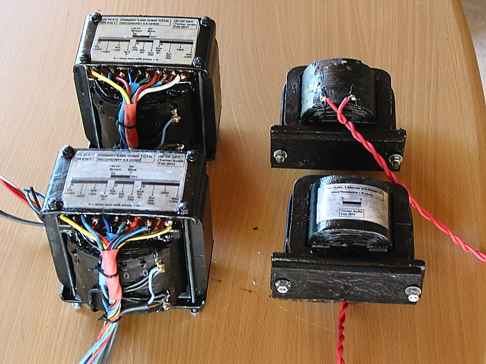
These are the OPTs and chokes I supplied.
The OPTs have GOSS C-cores. Secondary has 9 sections of one wire
layer each, and all
sections are paralleled. Primary has 8 sections with 2 layers of
wire each, and each P section
is between the S sections for interleaving pattern of 9S x 8P, ie
17 total sections using a total of
25 layers of wire. Insulation is 0.2mm polyester.
6 primary sections are used for the anode winding and it has taps
for ultralinear use or bootstrapping.
2 primary sections in centre of winding build up are used for 25%
local cathode feedback.
The amount of local CFB for the tubes is nominally 13dB with the
loadings shown in Fig 1.
This means the effective Ra of the tubes and their THD/IMD is
reduced to less than what would be
achieved if the tubes were triode connected and without the CFB.
Graph 1. Po vs RL at OPT sec.
The graph tells everyone what to expect with a quad of EL34 in an
output stage under
following conditions:-
Ea = 450V, Eg2 = fixed + 300Vdc, Fixed Eg1 bias, 25% CFB OPT CFB
windings,
or use 40% standard UL taps.
OPT gives 5k0 : 5r4. The graph assumes total of primary plus
secondary winding resistance = 5%
where sec is loaded with 10r0. This means that when sec load =
5r0, expect Rw total = 10%, and
with sec = 2r5, expect Rw total = 20%. The total Rw percentage
equals the amount of output
power generated by tubes that is lost as heat in the OPT windings.
With 10r0 sec load, the 4 x EL34 produce 40W while the output at
OPT sec = 38W.
But such losses are benign, and quite low, so there is nothing to
worry about. Because the OPTs for
Mr Z have C-cores with big winding windows relative to Afe, the
total Rw losses are probably lower
than I have assumed here. The conclusion is that any speaker load
with nominal Z above 3r0 is just fine
with 4 x EL34, or a quad of any other large octal output tubes
such as 6CA7, KT66, 6L6GC, 5881,
807, 6550, KT88, KT90, KT120, KT150.
However, use of tubes other than EL34 and their equivalent 6CA7
require more negative Eg1 biasing
of grids for the same idle Pda.
Global Negative Feed Back.
Fig 1 shows the use of about 10dB GNFB, which many people will say
is optional.
With the local NFB in the CFB cathode winding at OPT, there is
enough NFB to not have to use
any more, ie, the GNFB loop from OPT sec to one of two input grids
of the input pair of triodes.
This is because the Rout of the output stage with 25% of CFB when
the amp works in class A at all
low levels normally used, is less than pure class A triodes, so
damping factor > 4, and and bandwidth
> 20Hz to 20kHz, and THD < 0.2%, and benign H.
But when GNFB is used, there is need for LF and HF gain shelving
networks between V2 and V3.
Values shown are only theoretically correct and ONLY suit the OPT
properties used in this case, so if
YOU build any amp with GNFB, be prepared to test the amp correctly
and optimize stability networks
lest those shown here make the amp oscillate worse than when
values are optimal.
For HF stability with GNFB, see network C5&R10, to reduce the
HF gain above 50kHz, C2 across
R5 must be carefully chosen, There are Zobel networks across anode
windings, C15+R41, C16+R42,
and across OPT sec C18+R43.
The Zobel networks load the amp with resistive loads above 32kHz
so that there is always a load at HF
regardless of speaker properties.
The HF networks only work above 50kHz so make no difference to
music content below 20kHz.
For LF stability, with GNFB, see networks C8&R12, C9&R15,
to reduce gain below 15Hz.
Strictly speaking, these networks should be removed when GNFB is
not used. However, the amount of
attenuation of low bass in music is negligible, so they can be
retained.
Mr Z has selected to not use NFB. He is delighted by the sound,
because he says he preferred the
"open sound."
Testing the amp for unconditional stability with GNFB is
essential.
The amp must not oscillate at LF or at HF with no load connected,
or with any load of pure C between
0.05uF and 5uF and tested at any power level, including at very
low F < 20Hz when OPT is saturating
at high Va-a levels. The amp should be tested with 5kHz square
wave, and overshoot with any C load
should not exceed +6dB and ringing F amplitude should decline to
zero within 50uS. A typical tube
amp might produce some ringing F of say 70kHz with say 0.22uF
across OPT sec. This is OK because
the amp is effectively a second order bandpass filter. But when
there is pure R loading, there should be
negligible ringing.
If the amp does not oscillate with any pure C load, but has some
ringing with square waves, it has
correct critical damping and it will never oscillate with any
known speaker load. The useful test for
tolerance of ESL speakers is to use a dummy load with 16r bypassed
with 1r5 in series with 2uF.
ESL present low impedance loading at HF. So if testing with this
network, never use more than 1/10 full Po,
which is about 1/3 of clipping voltage Vo levels. The full power
response with GNFB and pure R load
should be between 14Hz and 60kHz at least. Loading by the Zobel
networks across OPT will reduce
max possible Po above 50kHz. At LF, effects of OPT core saturation
limit usable full Po. The saturation
F is proportional to OPT signal voltage. So at 1/2 Vo, -6dB, or
when there is 1/4 full Po, F response
should be from 7Hz to 65kHz with THD < 2%.
The Rout and THD without GNFB is low enough to not have to use the
GNFB. So indeed the sound is
OK without the GNFB for many ppl. Mr Z used his own design for
PSU, and to me its a bit "over the top"
but it does give noise free Vdc rails, so noise at the output
without GNFB would be negligible.
My Fig 1 schematic begins with V2a and v2b. So where is V1?
V1 would be included had Mr Z wanted an inbuilt pair of line level
preamps. Without GNFB the amp needs
only 0.44Vrms input for 62W into 5r4 load. Mr Z has 3 x RCA input
per channel and uses a rotary source
select switch and two gain pots - not shown at Fig 1.
There is a schematic for preamp input stage at bottom of this page
at Fig 3.
V3 and V4 are halves of a 6BL7 twin triode which works as a
balanced amp with 5k6 from common
cathodes to a -100Vdc supply. The dc RLdc resistors to 6BL7 anodes
are connected to taps on anode
winding of OPT. The taps supply +450Vdc, and also Vac which is
same phase as anode signal.
The anodes have a "bootstrapped" anode RLdc load. This means the
anode loading is much higher than
if RLdc was taken to a fixed B+. This means the maximum Va swing
with low THD is more than the 90Vrms
shown for clipping levels.
I did recommend Mr Z used paralleled 6SN7 or 6CG7 for the V3, V4
balanced amp.
But a 6BL7 has two triodes within and each 6BL7 triode can do
about what 3 triode sections of 12AU7,
and with less THD, so use of 6BL7 is very good.
Fig 2. Mr Z's PSU.
I have taken liberty with the original drawing Mr Z tendered after
he designed it.
I have just integrated the various B+ and B- supplies so that the
0V rail is more understandable.
MR Z explained......
"""In Australia there is a M.E.N. system which uses three
wires. Active goes directly to
the fuse for safety, thence with the neutral to an RFI filter,
which is contained in a die-cast box.
A DPDT switch with a HV cap across each set of contacts
goes through a thermal cut-out bonded
to the chassis. This supply goes to all mains transformer
inputs. When switched on, power is applied
to all heaters whether via a regulated supply (for preamp &
driver tubes) or direct from dedicated
windings on the toroidal transformer (power tubes are
referenced to ground via 39 ohm resistors.)
The B+ supply is also energized upon switch-on from dual
windings on the toroidal transformer.
A one ohm resistor limits surge currents going into the double
Pi filter, which is protected by a
500mA fuse. A dual RC network pre-filters the screen supply
before cascading into a split RC
network that supplies the anode loads of the 6DJ8 tubes.
The screen supply is regulated by a 317 regulator
protected by a MJE340 transistor and 15V
zener combination to give an output of ~300V. The regulator
output is loaded by a 300V zener
string until the screens are switched on.
Grid bias is applied also and cascaded into a 337 negative
regulator to supply the current source
and tail resistor of the 6DJ8s and 6BL7s respectively. The
one-shot circuit based around the 555
timer is also energized upon switch-on and a timer begins by
using the combination of the 10M
and 10uF capacitor to activate the relay coil after
around 110 seconds. Once the relay is activated
it switches the actual screens to the 300V supply. Also it
connects the 96V
supply to the driver and preamp tubes.""""
Now for those willing and able to relate what is said here to the
PSU schematic, they may see that I might
do things slightly differently. The fundamental point to remember
is that there is always more than ONE way to
build a PSU. There is other information on PSU at my relevant
pages for PSUs and large power amps.
Other pics of work in progress.......
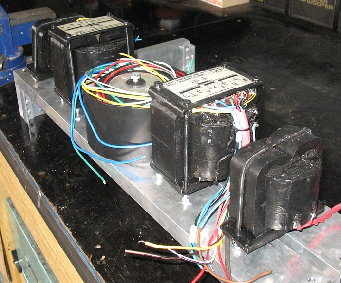
The B+ chokes are at each end of chassis, then a pair of OPTs and
a large toroidal PT in center.
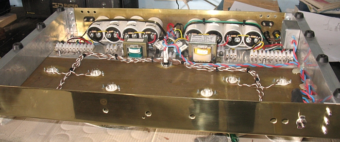
Work under chassis underway...
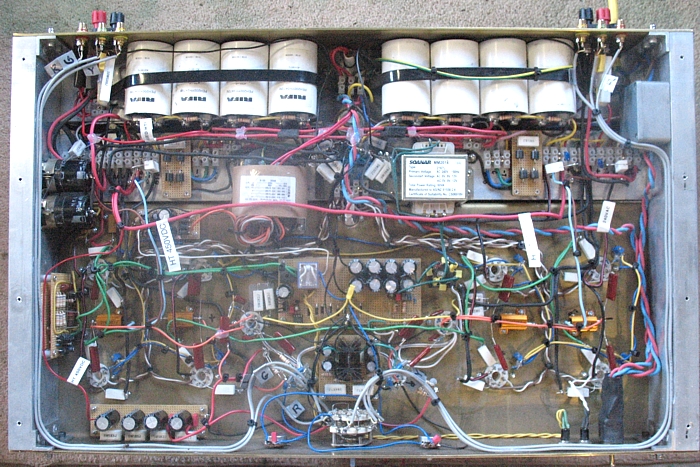
Point to point wiring.
With all such DIY projects, if you make the chassis large enough,
there is room for for everything
you think about after you done an initial schematic and after have
made the chassis. Many DIYers
cram the parts into a small chassis and create an amp with poor
access to parts later. So better that a
chassis is bigger than what might be used by a brand manufacturer
who has paid an accountant
to remove quality and reduce labour and material costs to
negligible fraction of the price people pay
in shops.
Fig 4. Preamp input stage for integrated power amp.
Well, plenty for everyone to think about here.
Additional ideas about 80Watt AB1 PP amp designs using a quad of
output tubes is at :-
80 W AB1 amp.
Back to Power Amps
Directory.
Back to Index