Reformed
Jadis 300B SE monobloc amps Nov 2012.
Edited 2017.
In 2012 a customer purchased a pair of second hand Jadis SE300B
amplifiers officially rated for 10W.
Here is a picture of original 1993 Jadis SE 300B amps....
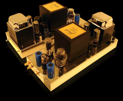
These mono amps were made in 2004 and the picture shows them
without their two metal cages with Allen bolts
to fix them over the 2 rectifier tubes at rear and 2 x 300B + 6SN7
at front.
The description from Stereophile included this :-
"""""Tube complement (each): 2 x 300B, 2 x 5R4, 1 x 6SN7.
Output impedance: adjustable, for 1–16 ohms.
Output power at 1kHz for 0.3% THD: 10W rms (10dBW).
Power bandwidth at 8W: 40Hz–15kHz – dB; 40Hz–30kHz
–3dB.
Input sensitivity for rated output: 450mV rms. Input
impedance >100k ohms.
Power consumption 140W each.
Dimensions: 8" (203mm) W by 9" (229mm) H by 20.5" (521mm)
D. Weight: 65 lbs (29.5kg).
Price: $13,000/pair (1996); no longer available (2012).
Manufacturer: Jadis S.A.R.L., Villedubert, France. """"""
Unfortunately, the information above is rather misleading for the
two amps which were brought to me after purchase
by the owner who said there was bad hum in one channel. He wished
that I fully examine them to ensure they would
be reliable and provide fine hi-fi.
Problems were :-
(1) I found the hum on one amp was due to the 0V rail being
directly connected to chassis. When the 0V rail was
re-connected to chassis through a 22 ohm R, hum was much reduced.
The other amp didn't make hum, but both
were given 22 ohms which Jadis should have used. Then I found many
other design shortcomings and very serious
design mistakes and quite unacceptable quality control for the OPT
and the B+ filter chokes.
(2) Just one common 5Vdc x 2.4 amp DC supply for both 300B.
(3) Just one common R&C cathode bias network for both 300B
with Ck = 4 parallel x 47uF/450V, ( OK ) and
Rk = 300r ( Not OK ), although 300r = 9 x 2k7 w/w vitreous enamel,
each 4W.
(4) Two silicon diodes were soldered to 5U4 B+ rectifier tube
socket for B+ supply to the pair of 300B.
These diodes were shunting the tube diodes, so this 5U4 was doing
nothing except produce wasted heat.
The 5U4 is rated for use with C1 = 40uF and if HT Va-a = 600Vac,
then expect +335Vdc at 150mAdc.
The data suggest that if Va-a = 670Vac, which is the Jadis HT
value, you'd get +374Vdc at 150mAdc.
But Jadis have 470uF + low value choke + 470uF as the CLC, and
Jadis had 5U4 charging 22uF then 10r
before the 470uF etc, so tube diodes would have not lasted long
due to excessive peak charge currents, so I can
see why Jadis must have abandoned the idea of having a tube
rectifier for the 300B supply.
With a tube rectifier, Ek = approx +55V, Ea = approx 310V, B+ =
365V, Ia 183mA. Because Si diodes had been used,
B+ was raised to +430Vdc regardless of whatever increase in Ia.
With Rk = 300 ohms,and Ra for both 300B = 350r,
and with Rk at 300r, effective total Ra at dc = 1,550r, so
increasing B+ by +65Vdc increases Ia by 42mA to 225mA
so Ek = 67.5V, Ea = 362V, so each tube has Pda = 40.7W. So just
adding the Si diodes without the increase of Rk would
soon cook the 300Bs to death, and of course they don't stay
matched, so one runs hotter than the other, and soon they fail
from too many cycles of running too hot. While the Rk of 300r
would be OK in theory with a tube rectifier, its no good in
the Jadis.
In the one amp which did work a bit, the Ia difference was 50% and
one 300B was far too hot, one was cool.
0.16 Amp fuses were fitted between each 300B anode and the OPT
primary. With Ia at 160mA, and Ea at 300V, Pda = 48W
before a fuse blows so 300B can become damaged before the fuse
blows. It seemed to me the soldering style was the same
at the diodes as for the rest of the point to point wiring, so I
suspect it was done by Jadis and not the previous owner or by
other ignorant idiot.
The other amp kept blowing anode fuses after turn on. The 300B had
become already damaged internally by excessive grid
heating which makes the grid wires become deformed. 300B have grid
wires arranged as a rectangular helical tube, and wires
have a straight length which tends to become bowed after grids
have been overheated. Eventually, such deformation causes
arcs between anode and grid or between cathode and grid. 300B are
nice tubes, but are very fragile compared to using a KT88
strapped as a triode.
(5) The 6SN7 has two triodes, one for input stage and other for
driver stage and both stages had identical set up with RLdc
= 150k, and fed from a +400Vdc B+ supply rail from a second HT
winding and 5U4 rectifier.
No silicon diodes were used to boost the B+. Ia in each 1/2 6SN7
was about 1.5mA only, rather too low. The 300B require up
to about 55Vrms of drive voltage at their grids. The 6SN7 single
driver triode struggles to make this amount of drive voltage with
low
THD.
(6) No global NFB was used so that output resistance is too high.
Anode loading was too low so THD was high at full power,
if full power could be obtained, ie, if the 2 x 300B each had
equal Ia. As the amps were, the one which barely gave 10W had
THD too high.
(7) The anode load for each 300B for maximum PO would have been
about 2k0. With 2 tubes, primary load total = 1k0, including
OPT winding resistance of approx 5%. With OPT set for "4 ohms" and
a 4 ohm load, OPT TR = 14.9:1, so ZR = 222:1 so RLa
= 888r + 44r for Rw = 930r, a trifle LOW.
So really, there is not a good match for 4r0 because most 4r0
speakers have minimum Z of maybe 2.5r within the main power band.
OPT has 4 secondary windings which may be re-arranged in
series-parallel to give a range of turn ratios of 29.8:1, 14.9:1,
9.9:1.
and 7.45:1.
These give load matching according to the following table :-
4 // N = N
|
29.8
|
888
|
Sec load = 1.0r
|
RLa = 932r
|
2 // ( N +N ) = 2N
|
14.9 |
222
|
Sec load = 4.0r
|
RLa = 932r |
N + N + ( N // N ) = 3N
|
9.90
|
98
|
Sec load = 9.5r
|
RLa = 932r |
N + N + N + N = 4N
|
4.45
|
55
|
Sec load = 25.9r
|
RLa = 932r |
Now with the extra high Ea, the Ia should have been allowed to be
lower by raising Rk from 300r to about 500r at least and
then the load values for full power need to be twice those shown
in the table. I have used dual Rk of 1k0, giving Ea = 355V,
Ia = 70mA, Pda = 25W, and tubes are comfortable.
The amp had OPT strapping set for 9.5r, and so speaker needed to
be 16r0 with raised Ea. With amp set for 4r0, amp needs
to have 8r0 load.
There isn't really a good 4r0 match possible if the original OPT
is used.
With silicon diodes at rectifier tube the B+ is higher and it
becomes obvious that it is so very easy for these amps to be used
by
an ignorant stupid audiophile who doesn't have any idea about load
matching and he manages to overload and damage the tubes.
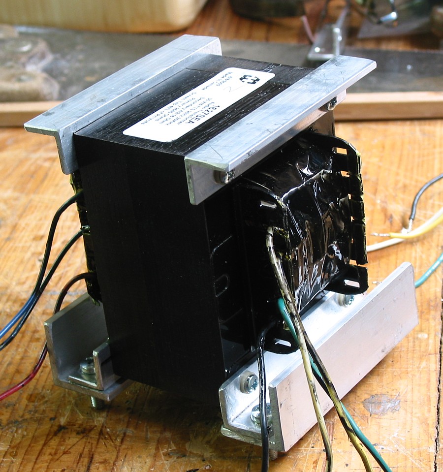
(8) The OPT in BOTH amps were found to have NO AIR GAP !!!!!!! ?
After modifying the circuit so that each 300B Eg1 bias voltage
could be adjusted,
I was able to get both Ia equal and not too high and then measure
the amp audio performance. I could not believe what I was
measuring with bass response because it was the worst I have ever
seen in any SE amp. So I tested the OPTs when connected
up to an external test circuit
as follows :-
As you can read from the image info, the usable response was
effectively between 220Hz and 25kHz.
Lp was measured at 50Hz to be 1Henry when it should have been
about 20H. The core was quite saturated with Idc at
160mA. With no Idc, Lp became 81H, so obviously there was no air
gap, and laminations are fully interleaved as for a
PP OPT.
(9) The B+ rail for 300B had CRCLC filtering arrangement. C1 =
22uF, R = 12r0, C2 = 470uF, L1 < 50mH, C3 470uF.
I removed the E&I laminated chokes which have low Rw = 15r,
quite low, indicating very few turns. Core size has
Tongue 22mm x Stack 20mm, so a tiny choke. I pulled the the choke
apart and found air gap = 1.5mm, and 10 times
higher than what it should have been after a few calculations. I
adjusted the gap down and re-tested the L and increased
it to 0.8Henry with Ia at 150mAdc. The choke could have had Rw =
30r0 using thinner and more turns which would have
given L = 2H, but 0.8H was a vast improvement. With Silicon diodes
there was no need for C1 of 22uF, so I removed this,
but replaced 12r0 with 18r0 x 10W placed between HT CT and 0V, so
that diode charge currents are limited and to
prevent switching spikes in 0V rail finding their way into audio
paths. So filter became C1 L C2 with 100Hz Ripple
voltage at C1 470uF = 0.6Vrms and at C2 = 4mV, and quite
acceptable for connection to the OPT primary.
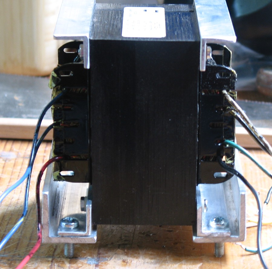
(10) The huge oversize Jadis power transformer is twice the weight
it needs to be. There are two HT windings one for
the +440Vdc rail for 300B, and the other for the +400Vdc rail for
6SN7. Both are adequately rated. The lesser HT
winding could supply perhaps 40mAdc easily if someone wanted to
use an extra and separate driver tube such as EL34
in triode so that the 6SN7 could become a stand alone paralleled
input tube. Such a better arrangement is what I would
expect after paying so much.
Then there are 4 low voltage secondaries, 2 x 9.6Vac, and 2 x
5Vac, all rated for 4Amps. 1 x 9.6Vac is rectified to
make 12Vdc and followed by series SS regulator for 5.0Vdc for both
300B. The regulator was on a heatsink under the
OPT in the chassis space, and it liberated about 12W. The other
9.6Vac is used for making a regulated 6.3Vdc for input
6SN7. 5Vac windings are for the 2 x 5U4 cathodes.
I decided each 9.6Vac windings would be used for individual
separate cathode heating of 300B so separate R+C
bypass networks could eliminate the very poor biasing the amp has.
Instead of 2 regulators I used CRC with R on
heatsink placed where 5u4 used to be. Also on the same much larger
heatsink positioned for much better ventilation
and less heating effect on sub-chassis items, I placed the 2 x 1k0
Rk to each 300B. So, heat is now managed better.
(11) I found the amp had 2 x 160mA anode fuses for the pair
of 300B. They didn't blow until damage was done in one
tube and then the other would blow just after. Mains fuse would
not blow unless something much worse occurred.
Blown fuses under the chassis were difficult for an owner to
replace, and 160mA is not a common value. I abolished
these damn fuses!
I have installed active protection by monitoring cathode current
with 22r between each R&C cathode bias network
and 0V, and have provided 2 test points on the side of the amps so
that Vdc across 22r may be measured without
moving the amps. With Ia = 70mAdc, V 22r = 1.54Vdc. Its a safe
measurement to make and if anyone shorts the test
point to 0V, it won't kill anything or anyone.
-----------------------------------------------------------------------------------------------------------------
I decided to remove both 5U4 and the 2 sockets. I have replaced
then with 8 x Si diodes under the chassis.
Using pairs of 1N5408 in series, Current rating allows 3A and PIV
rating is 2,000V, so they are going to last OK,
and if a short occurs, a mains fuse will blow, and not the diodes.
Where the tube rectifiers were, I have mounted a
heatsink for both 2 x 1k0 Rk for 2 x 300B and 2 x 5r0 for CRC
filters for two 5Vdc cathode heating supplies for 300Bs.
The 2 x 5Vac windings have been seriesed and the 10Vac rectified
to make 6.3Vdc x 0.6Adc for 6SN7 heaters.
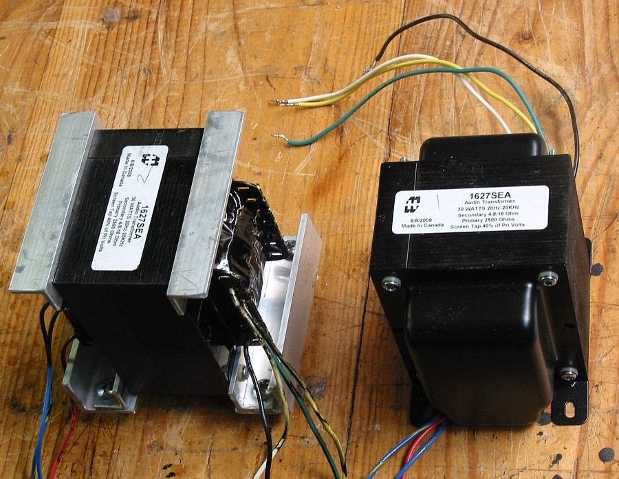
I removed both Jadis OPTs and replaced them with Hammond SEA1627.
These gave Lp = 18H at low level signals,
and Z matches of 2k5 : 4r0, 8r0, 16r0. Using the 8r0 tap, and
using load = 5r3, Po max was nearly 16W, so that at
least 10W was available for any load between 3r0 and 11r0.
This was a far better outcome than the original Jadis OPT.
Bandwidth was much wider. I removed bell ends from
Hammond OPTs then fitted AL angles for mounting with new pots the
same size as the pots around Jadis OPTs.
I used a 50:50 potting mix of casting resin + sand to make a
concrete around OPTs. So the amps will still look fine.
There will be a note glued to rear of OPT about what's inside.
Load match changes will probably never have to be
made, but now it means just moving ONE WIRE from the output
terminal to one of 3 available taps while using a
soldering iron. The original change of load match required
altering pattern of strapping held with 8 x 4mm nuts on bolts.
2 new straps needed to be made.
The RLa anode load with sec load = 5r3 is 1,656r + Rw of 132r for
total RLa = 1,788r so each 300B has a
theoretical load of 3,500r about twice the original design load so
damping factor is much better and THD much reduced.
Only 2 of the original 4 x EH300B remained usable during many
tests. The other two destroyed themselves.
I fitted 22r current sensing R to check Idc and Iac in the 2
usable 300B with individual Rk biasing. The difference in Iadc
and Iac was less than 10%, far better than when tubes shared the
same Rk. The difference in Iac means that one tube
produces different load current than the other for the same Va so
the loads each tube is effectively working with is different.
As long as the RLa for each does not vary by more than 10%, all is
well. The condition of grid and emission of cathodes
affect the load power of each tube.
The two bad 300B degraded during testing and both would arc
between grid and anode. Eg1 would rise to +330Vdc,
Ik would then rise, and rise, and eventually an anode fuse would
blow in one tube then the other. I watched and turned off
the amp. With active protection fitted the turn off becomes
automatic. These 2 tubes thus became rubbish.
But at least 2 x EH300B did work OK well enough and music was
quite splendid after totally gutting the amps and re-wiring
everything as the new schematic shows :-
SHEET 1. Monobloc audio amp.
I hope the above schematic shows enough details to allow anyone to
build a good 16W SET amp with a pair
of 300B. The unusual feature above is the use of a constant
current source for V1B driver triode's anode supply.
If a DC carrying R was used for 5.1mAdc, the value would have been
34kohms. But then the load offered by
the two following parallel 150k grid bias R17, R18 would have made
total DC and CR coupled load = 26k,
and this a value I consider too low to get my wanted best
linearity and wide voltage swing using just 1/2 of a
6SN7, and while keeping Iadc at a healthy 5mA, and have Ea high
enough to get the swing of 70Vpk.
So, with a CCS DC supply, the load is only 75k for R17, R18, and
then the distortion is much reduced and
the single triode just works a lot better. The input 1/2 triode,
V1A, did have Rdc to anode of 150k, same as the
V1B. I thought the Idc of less than 2mA was too low for both the
identical stages for input and driver.
But the input need only generate a small voltage, and so a
moderate rise in Iadc was called for, without
reducing the total anode load ohms too much, so you see my result
of thought. The sound from any any amp
like this dependent on the sum of the integrity of all aspects of
design, including finer points of the way input
and driver stages are set up.
SHEET 2. Power supply.
The power supply shown uses the original Jadis power transformer
which looks suspiciously like it may
have been meant for some other amp requiring more power. It is
likely that if they do not sell all the amps with
higher Po, they try to use leftover PT in the next model made, and
the high price of these amps more than covers the
waste of more iron and wire than required, and higher weight and
shipping costs.
Solid state regulators were used to make the Vdc needed for
heaters. But when I decided to use TWO separate
5Vdc supplies so that EACH 300B had its own 5Vdc supply, I went to
the simpler arrangement shown with CRC
filtering. There is less to go wrong, and I needed one extra Vdc
supply than in the original amp. This meant using the
2 x 5Vac windings for heating 5U4 cathodes to make 10Vac which
gives 12Vdc at C8, and R8+C14 give the
6.3Vdc x 0.6A for a 6SN7. It occurred to me that if someone were
to replace the 2 x 300B with say 3 x EL34 in
triode, then the 2 x 9.6Vac windings could be used in series to
make 19.2Vac, and this means you'd get 6.4Vac for
each EL34 filament in series! I bet Jadis had not thought of this,
but it is possible, if one likes changing the chassis to
suit 3 x EL34, or better, 3 x 6CA7. Load line analysis tells me
about 18W is possible, with same Hammond OPT
and the same B+.
SHEET 3. Active protection and slightly delayed B+ turn on.
The protection circuit above stops Ek rising too much to damage
the 300B. There are those who think a
300B is a fine old rugged tube design. The 300B is damn well NOT
rugged !!!! They break real easy, and if
the tube is subject to severe grid input signal, the grid can
overheat and the fragile box-section grid wires can
become bent in heat and arcing can occur between anode and grid.
This happened to 2 x EH300B during
my tests. The original amp had just one 300 ohm Rk for both 300B,
and Ia was unbalanced and way too
high for at least one 300B. The standard type of 300B such as EH
has a maximum Pda rating = 40W,
and anything above 28W for class A is risky and after spending
huge amounts of dough on 300B, you
will want them to last "a long time" so I have them running with
Ea 350Vdc and Ia 70mAdc for Pda = 24.5W
at idle.
The owner replaced EH300B with the smaller version Emission Labs
300B who make different versions. Yes, they
do sound different, but there is ZERO certainty that EM 300B may
sound any better than the "Common Garden
Variety Sovtek 300B," or an EH 300B.
The smaller EM300B does look like a well made rugged 300B. Its
cathode takes much longer to warm up
than for EH, and seems less microphonic. EH300B, like so many
others, dings like a bell when you tap it likely
because the metal grid etc vibrate easily at bell type frequencies
and modulated the electron stream.
The EML seem far more rugged. The EML cathode has lower resistance
when cold, but when hot, the
cathode has almost the same R as EH. Don't ask me what EML have
done with cathode metal properties but
I do prefer a slow starting cathode. There are some who would
always say fixed bias is the only good way
to bias directly heated 300B, because the Eg1 -Vdc is well
established with Si diodes before cathodes
can conduct so high peak cathode currents after turn on and before
cathodes are fully warm up can be
avoided. But I many ppl have used cathode biasing with no
problems.
The schematic shows 1.54Vdc is normal at cathode R8 and R14,
points P and Q. If Vdc rises to +2.2Vdc,
then Idc = 100mA, tube Pda = 33W, and the amp must BE TURNED OFF
!!!! This is the ONLY solution
for a tube in class A which conducts too much Idc, and despite the
presence of the Idc regulating cathode
resistors 1k0 bypassed with 94uF. If Ek rises from the normal
+71Vdc to say 102Vdc, Ea = 324Vdc and
Ia = 100mA, Pda = 32W, and this is the official tripping point for
the Q1 SCR C106D.
In the 2012 edition of this page I showed a bi-color green-red LED
which can be installed to replace the
original 5mm single LED in holder at front of chassis.
I very much doubt anyone else has ever attempted the
re-engineering I describe here, and exactly what I did
in 2012 does not need to be perpetuated by anyone building a DIYer
16W amps with 2 x 300B in parallel.
So the SHEET 3 schematic has separate red+green LED. This
schematic could be used for an amp with
any number of output tubes because the SCR gate reacts to the
highest Vdc signal from any single cathode.
If only 1 tube of a dozen becomes faulty with too much Ia, the amp
turns off. The fault detection is simple, but
does not detect a tube which has Ia too low, or which has become
an open circuit, usually because the glass
cracks and allows air to get in to stop any anode current. If one
tube dies this way, it leaves only one working
tube which may or may not affect the sound.
To cover more possibilities of "How Shit Can Happen" required that
I install 2 test points to monitor points P+Q
to allow monitoring the Vdc across each 22r using an cheap
voltmeter on its Vdc range. Some owners just will
not cope with such a simple easy technical operation. But
condition of 300B can be checked now without moving
amp, turning it upside down on carpet, removing bottom cover, then
risking death from electrocution while
probing around. The two 160mA fuses in each 300B anode circuit
have been removed - there is no need for them
any more, and so now all risk of shock has been removed, and the
active protection will turn off the amp well before
Iadc reaches 160mAdc.
New circuit boards and terminal strips have been glued to chassis
with Selleys 401 Silicone, rated for 200C.
Not bad stuff. Screws hold some boards to stainless steel as well.
Boards are from 6mm hardwood marine ply
and strips are 12mm x 10mm hardwood. I have used 1mm copper wire
tracks for protect board, hooked under board.
Other terminals are 4g x 16mm long brass plated c/s wood screws
used for small cupboard door hinges,
usually easily available. The soldering iron heat cauterizes the
timber to stop it splitting over time. The effect
is that the screws are every bit as good or better than fancy
turrets in PCB boards. All timber has a generous
coating of polyurethane varnish applied. Come back in 100 years,
and the circuit should still be serviceable.
Everything under the chassis now operates a lot cooler because hot
running SS regulators are removed,
and replaced with generously rated resistors glued to heatsink
above chassis.
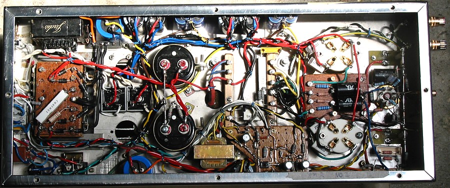
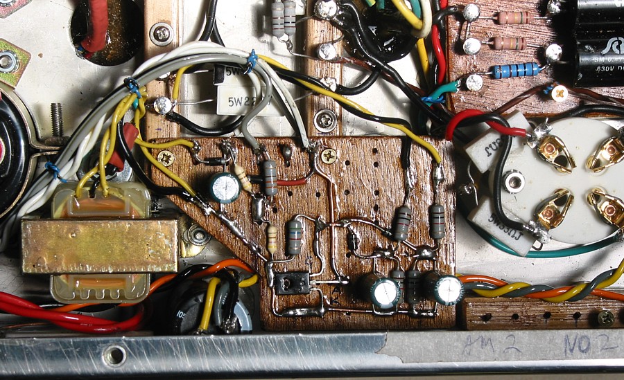
Here is the completely new wiring under the chassis. It is more
complex than the original chassis parts,
but allows better access to parts. Wires are lashed up tidily to
stop it all looking like a rat's nest.
GONE is the extensive use by Jadis of flying leads on stand offs
and other cheap nasty ways of
wiring and soldering.
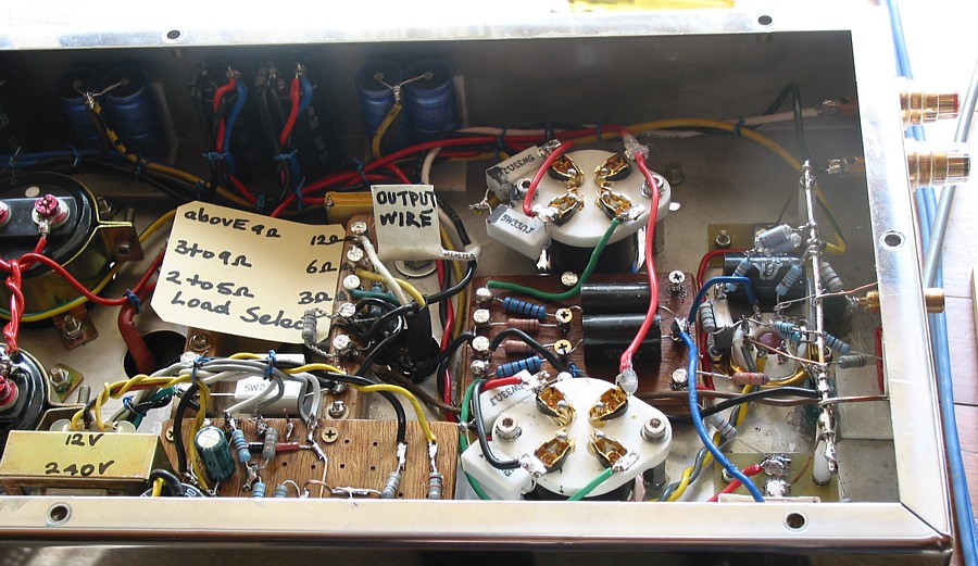
This shows the placard placed to indicate terminals for load match
changing. There is only ONE WIRE which
needs to be moved to suit the speaker to be used. Its now set for
6 ohms. But if someone had a speaker of
4 ohms with dip in band to 2 ohms, the 3 ohm terminal is best. But
a speaker with nominal Z of 4 ohms or above,
even 16 ohms, may be used at 3 or 6 ohm terminals. If 16 ohms is
used on 3r, power is limited to 5 watts,
but if speakers are sensitive like old Tannoy or are horn loaded,
the the 3r terminal should offer high enough
levels at the highest damping factor and minimum distortion.
Most people will never need to change from the
6r terminal. The amp could have had 4 rear binding posts, Com, 3r,
6r, 12r, but I could not easily source
bind posts matching those used by Jadis, so hence the adjustment
is made under-chassis. It thus is less
confusing for any owner. Owners have a terrible habit of always
using a 4 ohm speaker plugged in between Com
and 12r, and thus damaging music and their tubes. They only learn
through pain, and still never know anything
about ohms, resistance, voltage, current, or Ohm's Law. Better
that I minimize the likelihood of an owner
making a bad mistake. If a mistake can be made, you can trust an
audiophile to make it!
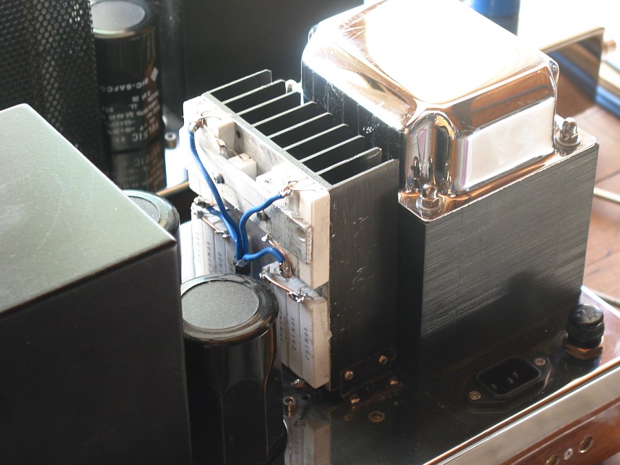
The above shows the heatsink above chassis for cathode biasing
resistors and the R used in CRC filters for
300B cathode heater supply. The original metal mesh cover box was
later fixed back over this heatsink.
Appearance is slightly changed with no 5U4, but it looks OK.
Black capacitors are rather nice quality 470uF x 450Vdc rated,
well selected by Jadis.
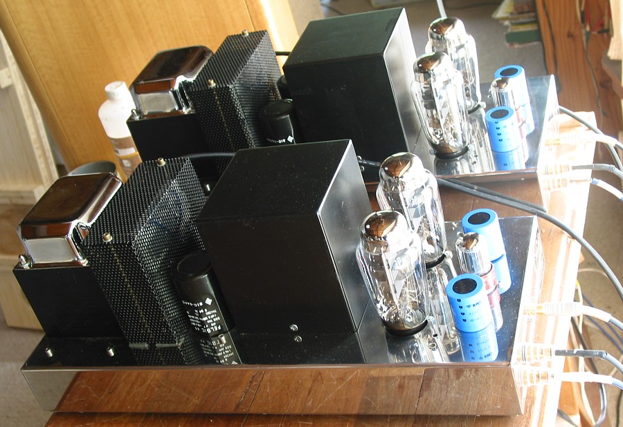
Here we see Emission Labs 300B plus NOS RCA 6SN7. Jadis had 4mm
dome head nuts on bolts
securing sunken ceramic tube sockets. But EML 300B have a rounded
shoulder on glass at bottom
of tube near tube base, and this prevented tubes being fully
inserted to sockets.
Dome nuts had to replaced with plain nuts with less height, and no
more fouling the glass on tubes.
The socket bolts reside in shallow slots each side of chassis hole
for 300B. In time, bolts could
sway out from slots to leave a dangling socket. But Jadis didn't
see the stupidity of not ensuring bolts
were through a hole, and not in a slot right near hole edge.
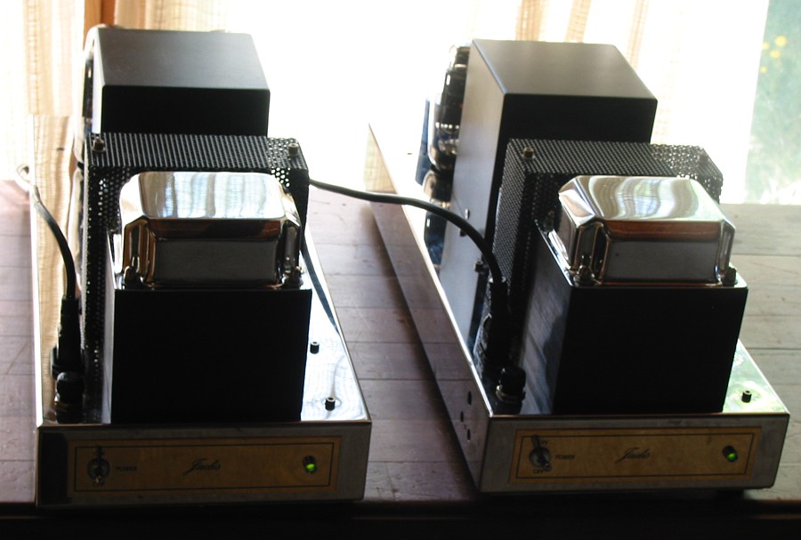
Power trannies on front of chassis are huge. They did get a bit
warm though, maybe Bac is a bit high.....
But now these amps can sing well. Notice that Jadis OPT badges are
missing from tops of new OPT
pots. Turned out Jadis pots had slightly concave tops, and badges
were also dished, but new pots
have slight convex shape so brass plate badges would not lay flat
nearly in silicone bed like on
original pots. In any case, screwing old badges down using 4 small
c/s M2 screws meant telling a lie.
Content inside pots wasn't made by Jadis, and the Hammond are much
better, and with the right air gap.
Two Hammond SEA1627 sit on my bench showing bell-ends have been
removed from one OPT,
and replaced with aluminium fixing angles prior to potting with
mix of dry sand and casting resin.
Sand was baked to remove moisture, then a 50-50 volume mix was
used. Sand settles in
liquid resin, so more is added to bring submerged sand level up to
minimize expensive
resin. The resulting concrete does not shrink much after it has
set, so steel
sides of pot do not come loose and buzz at AF from stray magnetic
field. But where any
buzz does occur, it is possible to drill a deep 5mm dia hole
beside inside of 4 pot sides,
and then pour a second small volume of resin only which should run
out into gap
between concrete and pot side.
Close up of fixing angles on OPT before potting.
Another close up of OPT before potting. The assembly dropped into
pot with sliding fit
and the M6 screws pointing upwards. Large dia washes with 8mm
holes were bolted down on
M6 screws, so that the larger angles were pulled up flush with the
edges of the pot.
OPT was then slid to centre position, and potting mix poured,
poked, pushed, and
cajoled into filling through just enough pouring gap between OPT
and pot.
After a day, 2 x M4 c/s screws were put through pot to vertical
angle.
The pot cannot come free.
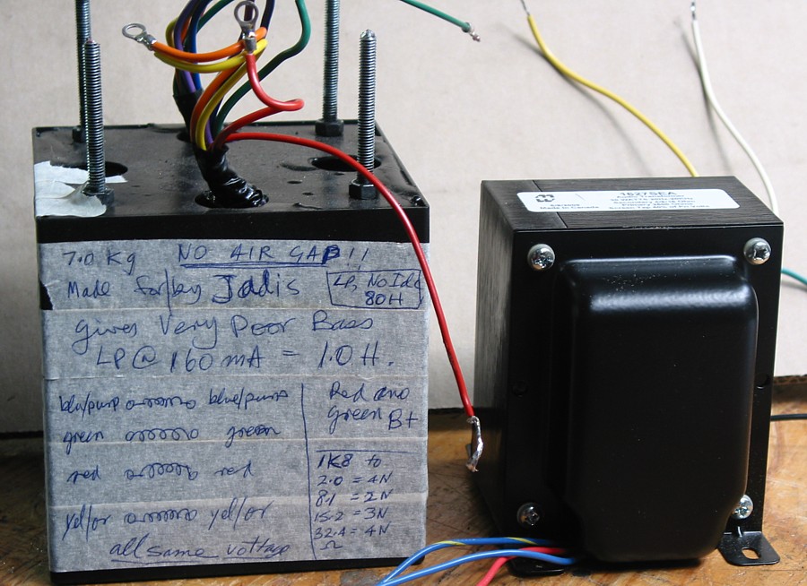
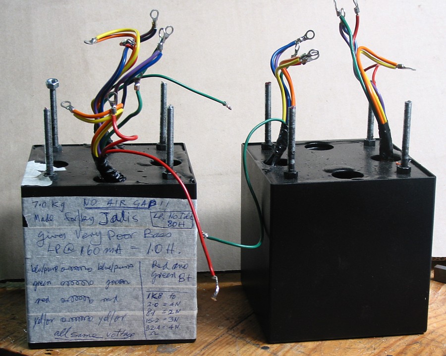
A pic of faulty Jadis OPT and a Hammond SEA. After weighing the
newly potted Hammond I found it was
about 1Kg heavier than the Jadis potted OPT, and I estimated the
Hammond has a higher core weight.
Pot size I happened to have laying around was 10mm higher than
Jadis pots, but 5mm less for each side size,
so internal volumes were near equal. Don't ask me what exactly is
actually inside the Jadis pot, but my careful
and repeated measurements indicate there is maybe a PP OPT which
has fully interleaved laminations, or C-cores
with no air gap. Hence it would be lighter weight. But if there is
a CT, it has not been brought out to amp.
If there had been a CT, I think the SE amp could have been easily
converted to a PP amp, using an extra
6SN7 twin triode for which there is plenty of room where tubes are
located. Class A PP 300B probably sound
better. I make no apologies for saying that, but really, its
almost impossible to make a bad sounding PP Plus,
PP operation gives the slight benefit of class AB, and 25Watts is
easily done, and OP tubes can be biased at only
20W Pda each.
There are TWO spare transformers from a real pair of what were
Jadis amps. They really do exist.
I ain't makin' up this story. Probably, the Jadis quality control
guy fucked up big time on these 2 amps.
It may only be these two amps, and no others, but I suggest anyone
who has Jadis SE300B amps should have
them tested by someone competent to find out if OPTs are crook. Of
course, finding a competent bloke on this
sort of thing IS DIFFICULT, and he won't be your audiophile friend
who "seems to know a lot".
The owner is now very happy with my work. He was using Atma-Sphere
OTL amps with their supposed
gloriously transparent sound, and "fabulous reliability", ( Never
mind so many are parked due to repeated
bias failures.) Well, after a few nights with my reformed amps, he
has sold his Atmas-Sphere amps. Hey hey,
another myth just hit the dirt !!!!
Do you realize what some audiophiles say to each other? Well, one
guy tells another some of the OP tubes in an
Atma-Sphere can be removed if there is too much volume because the
amp is too sensitive, or in fact the source
level is way too high so gain control works near the bottom of its
range. Less OP tubes means less volume, no?
makes sense, yes? Well no, because all tubes in all OTL are
working under duress and in class B and they
overheat with alarming regularity. Using less tubes mean even
lower levels of sound cause remaining tubes to
cook to death. Less tubes don't give less volume because levels in
OTL amps are subject to large amounts
of loop NFB, so fewer horses are flogged harder to maintain speed.
Well guy listening thinks, ah, I can remove one 300B to make it
quieter. Hmm, turns out guy has a Wadia CD
player with incomprehensible manual instructions for its digital
attenuator, which probably sounds no better than
a good 20k log pot, or a DACT switched attenuator, all despite the
Wadia sales BS.
I had to insist that the guy never ever remove any OP tubes in any
amp at any time ever lest he enjoy another
huge repair bill and bad sound. Folks, don't do anything I
wouldn't do. And don't do anything I would not enjoy.
Happy soldering to all.
To Re-engineered amps
To Educational and DIY directory
To Index