EAR509 100W monobloc amps, made 1979,
re-engineered 2003.
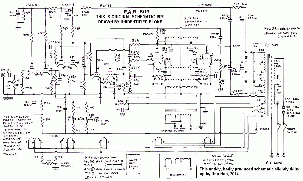
This is the only very untidily drawn schematic I could find for original
EAR509 from 1979:-

There are many design problems with this amp.
I had two of these monoblocs brought to me by a customer who
probably paid little for them. One had nearly
burned down a house, and was badly damaged by smoke and flames
under the chassis. Someone else had tried
to fix it, but amazingly they managed to lose the burned out PT.
I wound a replacement with identical windings to those in the
other undamaged channel, and I used GOSS E&I,
with same stack height, and using a matching bell end cover. This
ran much cooler than the original other channel
so EAR had not used GOSS in their PTs. Notice the terrible bias
pot arrangement which makes it very difficult to
set the bias properly. This is because the bias adjust network has
10k + 100k pot + 10k to divide the -160V
bias supply, so Vdc across 100k pot = 133Vdc. This means the range
of Eg1 is far too big for a small rotation of pot,
which will make many owners very angry while they try in vain to
set bias correctly, but find the tiniest pot rotation makes
tubes biased low or high, but rarely correct. This is compounded
because for PL509 with such high Ea and Eg2,
the Eg1 grid bias then has to be made very negative to keep Ia low
and below say 30mAdc.
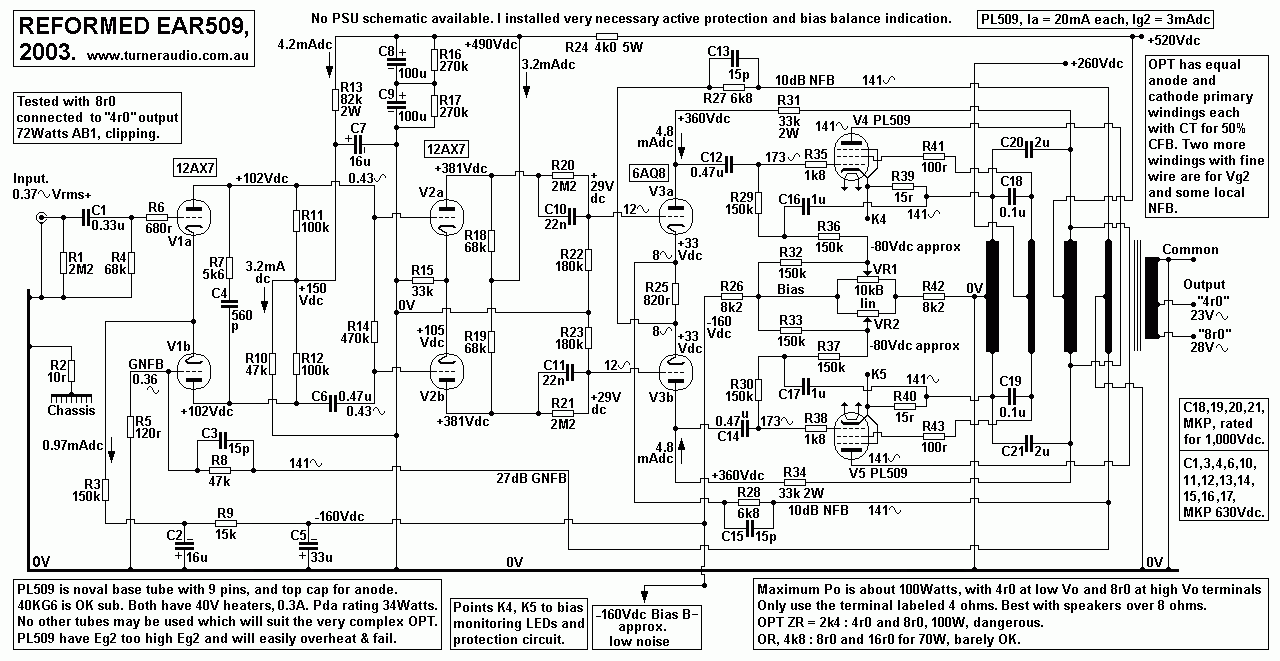
Here is my much better schematic :-
 My
schematic used the same tubes but with many changes to original
schematic. The amp works the same way as original.
The function is in fact very much like a McIntosh amp, with output
tubes working in what is wrongly called "unity gain"
where OPT primary winding for anode current is split into two
equal turn windings each with CT, one at B+ and for anodes
and the other at 0Vdc for cathodes. Thus there is 50% CFB applied
so that nominal gain is not unity, or 1.0, but over 1.0 and
less than 2.0. The amount of local NFB in output stage is about
12dB.
Unlike McIntosh, the screen +Vdc supply for PL509 is half the
anode +Vdc at +520Vdc, and screens are fed Idc from a
CT winding with same turns and phase as the cathode winding, but
using smaller wire size.
There is yet another winding with same turns and smaller wire size
as for the cathode winding used to supply local
NFB to cathodes of 6AQ8 V3a+b, and 27dB GNFB from one end of the
NFB winding to 12AX7 V1b.
Thus total NFB applied = 12dB + 10dB + 27dB = 49dB. This is an
enormous total amount of NFB and 28 times more
than the usual 20 NFB used in many other tube power amps.
The OPT Secondary winding is not included in NFB loops because the
leakage inductance would make it impossible
to get unconditional stability with such a huge total amount of
NFB. My listening tests did not show me that this EAR
amp was any better than a "normal" 40W UL amp with 20dB GNFB or
less.
The output tubes in this EAR amp are working in nearly class B,
and under duress, ie, being flogged too hard, and very
prone to failure.
PSU is not shown but was same as original amp but with all electro
caps replaced with better types. An active protection
circuit was added to counter the tendency of the PL509 to overheat
easily. Bias condition was balanced and monitored
with red-green LEDs adjacent to each PL509, (not shown).
The PL509 has a 40Vac heater and noval base which is similar in
size to octal tubes like EL34, but with 9 slender pins,
and not as good as octal.
Much better and more desirable and sensible tubes such as KT88,
6550, KT90, KT120 cannot be used without changing
2 noval tube sockets to octal, replacing PT, OPT, and making huge
change to PSU circuit, in other words, scrapping
all the dodgy efforts of EAR, and building something entirely
better.
The OPT anode and cathode windings are not bifilar wound as in
McIntosh, using triple insulated wire because there is
470Vdc between the two windings. The two windings do not need to
be bifilar wound, because the leakage inductance
between the two windings can be eliminated by use of shunt C
across ends of anode and cathode windings with the
same phase and amplitude of Vac. EAR used 22uF elcaps, but I found
2uF plastic caps were entirely adequate.
The screen winding with CT has same turns and Vac as cathode, but
has smaller dia wire because Idc to screens is much
lower than anode Idc. The same principle of C bypassing is used to
avoide effects of leakage inductance.
The anode winding at +520Vdc supplies 4.8mAdc to each anode of
6AQ8 V3a+b through 33k. Each anode is
bootstrapped to make each 33k look like a higher value RL and make
Ea effectively higher. The V3a+b cathodes have
10dB local NFB applied to that each triode of 6AQ8 is able to
generate Va up to about 200Vac.
The OPT appeared to have ZR = 2k4 : 4r0 & 8r0.
I recall I measured max Po = 100W.
The PL509 work mainly in class B giving very little class A. The
class B load for class AB working = 600r,
and Iacpk = 0.57A. There is no doubt the PL509 can deliver this
current.
For the above Ea/Ia conditions, Pda can be calculated using
formula,
based on Pda = P psu - Pout :-
To calculate AB1 Pda total, both tubes, for any value of PO,
Pda = Ea x [ ( 0.364 x Ia ] + [ 1.8 x Va-a / RLa-a ] + [ 0.364
x Ia squared / { ( 2.83 x Va-a / RLa-a ) - Ia } ] - Po.
Where Pda = heat in watts and total for both tubes,
Ea = +Vdc between anodes and cathodes,
0.364, 1.8, 2.83 are constants,
Ia = dc idle current for one tube,
Po = audio power out with THD < 2%,
RLa-a is anode to anode OPT primary load,
Va-a is signal Vrms across whole primary.
For this example,
Ea at high Po = +500Vdc, Idle Idc = 0.03Adc, Po = 100W, RLa-a =
2,400r, Va-a = 490Vrms.
Pda =
500V x [ ( 0.364 x 0.03A ] + [ 1.8 x 490V / 2,400r ] + [ 0.364 x
0.03A x 0.03A / { ( 2.83 x 490V / 2,400r ) - 0.03A } ] - 100W.
= 500 x [ ( 0.0109 ] + [ 0.3675 ] + [ 0.00033 / { ( 0.548 } ] -
100W
= [ 500 x 0.3790 ] - 100 = 189.5W - 100W = 89.5W.
The Pda rating for one PL509 = 35W, and for two = 70W.
The pair of PL509 would overheat and melt down to destroy
themselves with a constant sine wave signal producing
continuous Po = 100W.
NOTE. The old formula for a class B amp from the 1930s and from
old books may be written differently in terms of
Va-a, Ea, RLa-a and without PO to give :-
Total Pda for all output tubes = [ Va-a x ( {1.8 x Ea } - Va-a ) /
RLa-a
Applying to nearly class B EAR509,
Pda = [ 490 x ( { 1.8 x 500V } - 490Vrms ) / 2,400 = 83.7W.
The class AB use with 30mA idle current gives slightly more Pda.
Both formulas indicate Pda max for each PL509 = 41.8W, above the
allowable 35W rating.
You might say this is OK because music power does not equal sine
wave power, but if an idiot connects a 4r0 speaker
where labelled outlet is 8r0, the RLa-a is halved to 1,200r and
PL509 could quickly overheat.
Even with the "correct" 8r0 speaker at outlet labelled 8r0-Com,
the PL509 are being worked too hard so it is always better to
completely ignore the 8r0-Com and ONLY use the 4r0-Com terminals
for all speakers. I do not think 4r0 speakers should
ever be used with EAR509.
For home hi-fi, use of 8r0 speakers at 4r0-Com gives maximum Po =
72W, and this is plenty.
16r0 speakers may be connected at 8r0-Com for 72W, but it is
better to use the 4r0-Com for maximum 42W.
4r0 speakers may be connected to 4r0-8r0 terminals. The ZR = 13k5
: 4r0, and maximum Po = 32W.
The data sheets for PL509 show highest Eg2 at 190Vdc, and yet we
see them here with +260Vdc, and Ea at +520Vdc,
both about 33% higher than they should be for reliability. FOUR
PL509 tubes should have been used for 100W, NOT two!
With such high Eg2, the Eg1 bias must be a highly negative voltage
and is difficult to set correctly for PL509.
I compared the sound of EAR509 to a normal UL 50W amp with 2 x
KT88 and with fewer input tubes and only17dB GNFB.
The UL amp sounded much better and with none of the hardness of
EAR509. The EAR509 amp is an example of how not to
make a tube amp, IMHO.
Back to re-engineered amps
directory
Back to Index 
 My
schematic used the same tubes but with many changes to original
schematic. The amp works the same way as original.